
Introduction to the LT1050 12V System & Safety Mandates
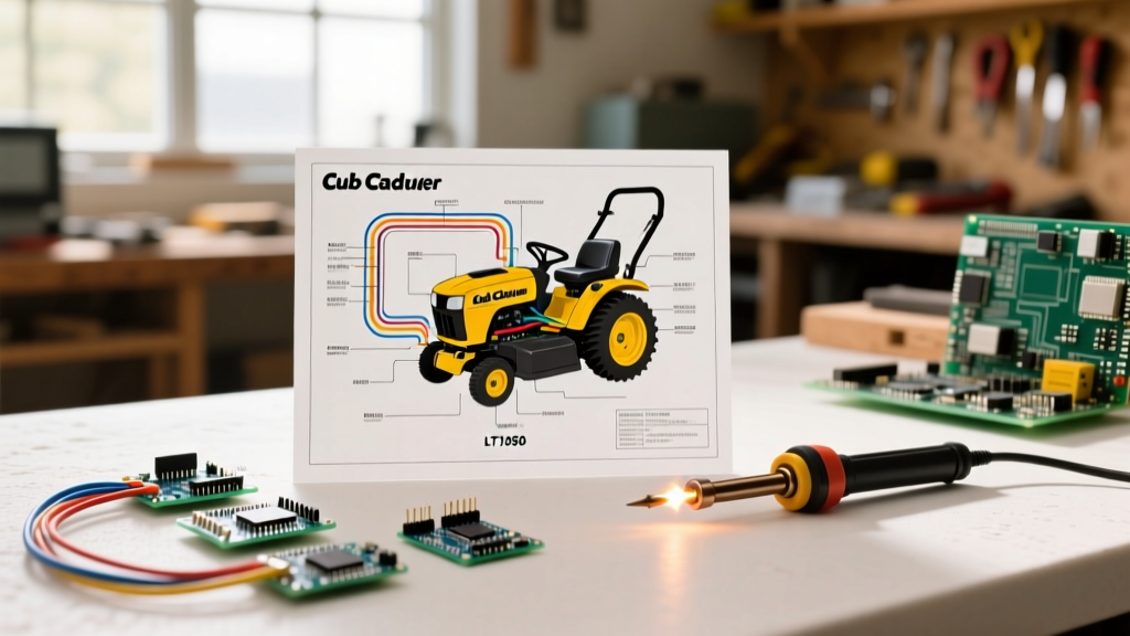
The Cub Cadet LT1050 is a staple in residential and light-commercial landscaping, typically powered by a Kohler Courage SV590 engine (19-20 HP). When electrical faults occur—ranging from a no-crank condition to a PTO clutch that refuses to engage—technicians and DIYers immediately search for the wiring diagram for Cub Cadet LT1050 models. However, blindly probing wires with a multimeter or bypassing safety relays to force a start violates critical outdoor power equipment safety standards.
As of 2026, the industry standard for riding mower electrical safety is governed by the ANSI/OPEI B71.1 standard. This code mandates strict operator-presence interlock systems. Bypassing a seat switch or brake switch to diagnose a wiring fault isn't just dangerous; it creates severe liability and violates Consumer Product Safety Commission (CPSC) guidelines for consumer lawn equipment. This guide provides a code-compliant, safety-first approach to reading the LT1050 schematic, selecting the correct SAE-rated wiring, and troubleshooting without compromising the machine's safety architecture.
Core Components in the Wiring Diagram for Cub Cadet LT1050
Before taking a multimeter to the harness, you must understand the specific architecture of the LT1050's 12V DC system. The schematic is divided into three primary circuits: the cranking circuit, the charging circuit, and the safety interlock/PTO circuit.
Ignition Switch Pinout & Terminal Logic
The LT1050 utilizes a universal-style 5-pin or 6-pin ignition switch. Misidentifying these terminals is the leading cause of aftermarket replacement failures and electrical shorts. The standard terminal designations on the diagram are:
- B (Battery): Receives constant 12V from the main harness (protected by a 20A inline fuse).
- S (Solenoid): Sends 12V to the starter solenoid trigger wire only when turned to the 'Start' position.
- I (Ignition): Powers the fuel solenoid on the Kohler carburetor and the dashboard indicator lights.
- R (Regulator/Alternator): Provides excitation voltage to the Kohler voltage regulator.
- G (Ground): Completes the circuit for the dashboard lights.
- M (Magneto): Grounds the ignition coils to kill the engine when turned to the 'Off' position.
PTO Clutch and Relay Logic
The LT1050 uses an electromagnetic PTO clutch (commonly an Ogura or Warner model). The wiring diagram routes power through a PTO relay rather than directly through the dashboard switch. This is because the clutch draws 2.5 to 3.5 amps at 12V, which would melt the contacts of a standard dash switch over time. The relay is triggered by the PTO switch, but only if the safety interlock module (or relay logic network) confirms the operator is seated and the brake is depressed.
ANSI B71.1 Compliance Warning: Never jumper the PTO relay coil directly to the battery to test the clutch. If the engine is running and the interlocks are bypassed, engaging the blades without an operator in the seat violates federal safety guidelines and risks catastrophic injury. Always test the clutch resistance statically with the engine off and the battery disconnected.
Wire Gauge & Routing Compliance (SAE J1128)
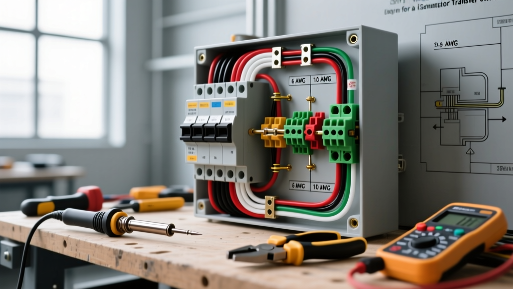
When repairing a damaged harness on the LT1050, standard household THHN wire or cheap automotive primary wire will fail prematurely due to the high-vibration, high-heat environment of the Kohler SV590 engine bay. Repairs must comply with SAE J1128 standards, specifically using GXL (General Cross-Linked) or TXL (Thin-Wall Cross-Linked) wire, which resists heat up to 125°C and abrasion.
| Circuit Path | Min. Wire Gauge (AWG) | Fuse Rating | Terminal / Connector Type |
|---|---|---|---|
| Main Battery to Starter Solenoid | 10 AWG (GXL) | 30A Main Fusible Link | 5/16" Heat-Shrink Ring |
| Solenoid to Starter Motor | 6 AWG or 4 AWG | Unfused (High Amp Draw) | 3/8" Heavy Duty Ring |
| PTO Clutch Feed | 14 AWG (TXL) | 10A Inline Blade | 1/4" Weather-Pack Spade |
| Ignition Switch & Dash | 16 AWG (TXL) | Protected by 20A Main | 0.250" Push-On Blade |
| Safety Interlock Switches | 18 AWG (TXL) | Protected by Main | Weather-Pack Sealed |
Step-by-Step Safe Troubleshooting Protocol
When using the wiring diagram to trace a fault, follow this sequence to prevent short circuits and ensure accurate diagnostics. According to Ohio State University Extension agricultural safety protocols, all electrical diagnostics on riding equipment must begin with energy isolation.
- Energy Isolation: Disconnect the negative (-) battery terminal first. This prevents accidental shorts if your wrench bridges the positive terminal to the tractor frame while working near the solenoid.
- Visual Harness Inspection: Trace the main harness from the battery to the firewall. Look for chafing against the steering column or heat damage near the Kohler exhaust manifold. The LT1050 is notorious for stator wire insulation melting where the harness zip-ties to the engine shroud.
- Static Resistance Testing (PTO): Disconnect the 2-pin connector at the PTO clutch. Set your multimeter to Ohms (Ω). Probe the clutch terminals. A healthy Ogura/Warner clutch will read between 2.5Ω and 4.5Ω. A reading of 0Ω indicates an internal short; infinite (OL) indicates a blown internal coil. In 2026, a replacement OEM PTO clutch costs between $95 and $130.
- Voltage Drop Testing (Live Circuit): Reconnect the battery. Set the multimeter to DC Volts. With the engine running and the PTO engaged, place the red probe on the battery positive and the black probe on the PTO clutch positive wire. A voltage drop greater than 0.5V indicates high resistance (corrosion) in the feed wire, relay contacts, or inline fuse holder.
- Ground Path Verification: The Kohler SV590 relies on the engine block for the starter motor ground. Place the red probe on the battery positive and the black probe on a clean, unpainted metal spot on the engine block. If you read anything less than 12.4V, the main ground strap is corroded and must be replaced with a braided copper strap.
Common Failure Modes & Code-Compliant Fixes
Understanding where the LT1050 wiring diagram typically fails in the real world saves hours of diagnostic time. Here are the most frequent edge cases and how to fix them without violating safety codes:
- The 'No-Crank' Solenoid Click: Often misdiagnosed as a bad starter. In reality, the LT1050's safety interlock network requires the brake pedal to be fully depressed to complete the ground path for the starter solenoid trigger. If the brake pedal switch is misaligned by even 3mm, the circuit remains open. Adjust the switch bracket rather than bypassing the switch.
- Blown 20A Main Fuse Upon Key Turn: This indicates a dead short to ground before the ignition switch. Check the wiring harness where it passes through the metal dash support. The vibration of the mower often wears through the 16 AWG harness loom, causing the 'B' (Battery) wire to arc against the steel chassis.
- Alternator Not Charging: The Kohler voltage regulator requires a clean ground to function. The regulator is mounted directly to the engine shroud. If the shroud bolts are rusted, the regulator loses its ground reference. Remove the shroud bolts, clean the contact patches with a wire wheel, and apply a thin layer of dielectric grease to prevent future oxidation.
- Seat Switch Bypassing: Some owners attempt to bypass the seat switch by jumpering the harness connector so the tractor can run without an operator (e.g., for spraying applications). This violates ANSI B71.1. If you need to operate the PTO while dismounted, you must use a factory-approved remote PTO kit or a commercial-grade sprayer tractor equipped with proper rollover protection (ROPS) and remote interlock overrides.
Final Thoughts on Schematic Accuracy
Always ensure you are referencing the exact wiring diagram for your specific Cub Cadet LT1050 model year and serial number range. MTD (the parent company of Cub Cadet) frequently updated the safety interlock relay logic between the 2006 and 2012 production runs. Using a 2008 schematic to troubleshoot a 2011 model will result in misidentified relay pins and potential damage to the Kohler voltage regulator. Keep a printed, laminated copy of your exact schematic in your service manual binder, and always prioritize SAE-compliant materials and ANSI-mandated safety interlocks during every repair.