
The Critical Role of Voltage Monitoring in DC Systems
Whether you are building a custom 12V RV dashboard, a 24V off-grid solar battery bank, or a DIY bench power supply, accurate voltage monitoring is non-negotiable. In 2026, the market is flooded with ultra-cheap digital LED displays, but a significant percentage of DIY electrical fires and component failures stem from improperly wired monitoring circuits. Understanding how to interpret and execute a wiring diagram for voltmeter installations ensures you get precise readings without introducing parasitic draws, ground loops, or fire hazards into your DC system.
This guide provides a rigorous, step-by-step walkthrough for the two most common DIY panel meters: the standard 3-wire digital LED voltmeter and the 4-wire shunt-based voltmeter/ammeter combo. We will cover exact wire gauges, fuse sizing, and the critical edge cases that generic manuals fail to mention.
Anatomy of the 3-Wire Digital Panel Voltmeter
The most ubiquitous panel meter in the DIY space is the 3-wire digital LED voltmeter (commonly sold under brands like Drok, Baike, or generic OEM labels). As of early 2026, these high-accuracy modules typically retail between $8 and $14. They feature three distinct wires emerging from the rear casing:
- Red Wire (VCC / Power): Powers the internal LED display circuitry. Requires 4V to 30V DC depending on the specific model.
- Black Wire (GND / Ground): The common ground reference for both the display power and the voltage measurement.
- Yellow Wire (Sense / Measurement): The high-impedance input that actually reads the system voltage. This wire draws virtually zero current (usually less than 2mA).
Expert Insight: Many beginners assume the Red and Yellow wires can be twisted together and connected to the positive terminal. While this will turn the meter on, it defeats the purpose of a panel monitor. If wired this way, the meter will read battery voltage even if your main system breaker is tripped, giving you a false sense of security regarding your load bus status.
Visualizing the Wiring Diagram for Voltmeter Connections
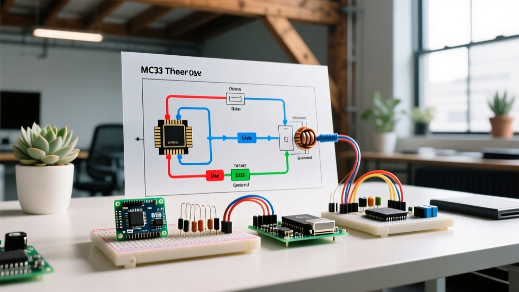
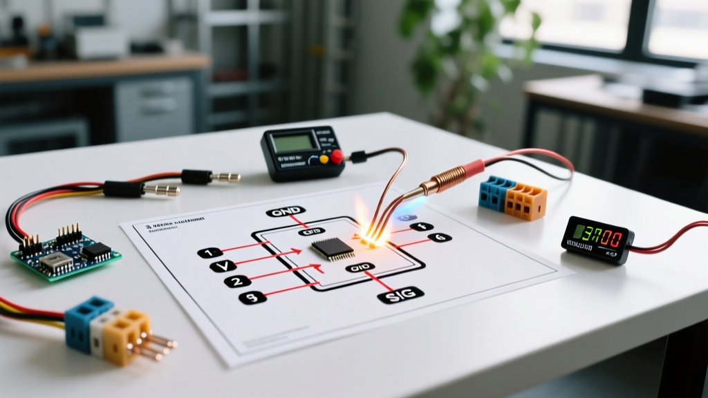
Before stripping any wires, you must mentally map the circuit. Below is the logical flow for a properly fused 3-wire installation in a 12V DC system:
- Battery Positive (+) → Main System Fuse/Breaker → Load Busbar (+)
- Battery Negative (-) → Main System Shunt (if applicable) → Load Busbar (-)
- Yellow Sense Wire → Taps into the Load Busbar (+) (Downstream of the main breaker)
- Red Power Wire → Taps into the Load Busbar (+) via a dedicated 2A inline fuse
- Black Ground Wire → Taps into the Load Busbar (-)
Step-by-Step Walkthrough: 3-Wire Digital Meter Installation
Step 1: Prepare the Sense and Power Taps
Cut a 6-inch length of 22 AWG stranded copper wire for the Yellow sense tap, and a 12-inch length of 18 AWG for the Red power tap. The sense wire carries negligible current, so 22 AWG is perfectly adequate and makes routing through tight panel bezels easier. However, the Red wire must handle the display's startup surge and should be protected by an inline fuse.
Step 2: Install the Inline Fuse
Crimp a 2A AGC glass fuse holder onto the Red power wire. According to Blue Sea Systems' circuit protection guidelines, every individual branch circuit—even low-draw monitoring circuits—requires dedicated overcurrent protection placed as close to the power source tap as possible. Do not rely on the main 100A system breaker to protect a 22 AWG meter wire; a short in the meter wire will melt the insulation long before the main breaker trips.
Step 3: Terminate with Ferrules
Never insert bare stranded wire into screw-terminal busbars. Use a wire ferrule crimper (such as the IWISS SN-48B) to apply 22 AWG and 18 AWG bootlace ferrules to your meter wires. This prevents stray wire strands from bridging the gap between the positive and negative busbars, which is a leading cause of dead shorts in custom DC panels.
Step 4: Execute the Connections
Connect the Yellow sense wire directly to the positive load busbar. Connect the fused Red wire to the same positive load busbar. Finally, route the Black ground wire to the negative load busbar. When you energize the main system breaker, the meter will illuminate and display the exact voltage present at the load bus, accounting for any voltage drop across the main breaker and primary cabling.
Advanced Walkthrough: Shunt-Based Ammeter/Voltmeter Combos
For systems requiring both voltage and current monitoring (e.g., solar battery banks or RV house banks), DIYers frequently use 50A or 100A shunt-based meters like the popular Bayite DC 6.5-100V 50A model (priced around $16 to $22 in 2026). These require a fundamentally different wiring approach due to the external shunt.
The Low-Side Shunt Rule
The most catastrophic mistake made with cheap digital shunt meters is placing the shunt on the positive (high) side of the circuit. These meters are designed exclusively for low-side (ground path) measurement. The internal operational amplifier references the shunt's millivolt drop against the meter's ground wire. If you place the shunt on the positive rail and connect the meter's ground to the negative rail, you will subject the meter's internal voltage regulator to the full system voltage differential, instantly destroying the silicon and potentially causing a localized fire.
Wiring the Shunt Combo
- Main Load Path: Route your heavy-gauge negative cable (e.g., 2/0 AWG) from the battery negative terminal to one side of the heavy brass shunt. Route another 2/0 AWG cable from the other side of the shunt to your negative load busbar.
- Signal Wires: The shunt will have two thin signal wires. Connect these to the corresponding terminals on the digital display head. Keep these signal wires routed away from high-current AC inverters to prevent electromagnetic interference (EMI) from causing the amperage reading to jitter.
- Display Power: The display head requires separate power. Connect the red and black display power wires to a fused 12V source. Do not power the display head directly off the heavy shunt terminals; use a clean, fused tap from your DC distribution block to ensure a stable voltage supply for the display logic.
For a deeper understanding of how shunts calculate current via Ohm's Law and millivolt drops, refer to this comprehensive guide on wiring voltmeters and ammeters by Electrical Technology.
Wire Gauge and Fusing Specifications Matrix
Proper wire sizing is dictated by the maximum current the circuit will carry and the length of the run. Use the table below as a baseline for your panel meter wiring in 12V to 48V DC systems.
| Circuit Segment | Recommended Wire Gauge (AWG) | Max Fuse Rating | Terminal Type |
|---|---|---|---|
| 3-Wire Meter Sense (Yellow) | 22 AWG Stranded | None (High Impedance) | Bootlace Ferrule |
| 3-Wire Meter Power (Red) | 18 AWG Stranded | 2A (AGC or Mini Blade) | Bootlace Ferrule / Ring |
| 3-Wire Meter Ground (Black) | 18 AWG Stranded | None | Bootlace Ferrule / Ring |
| Shunt Main Load Path | System Size (e.g., 2/0 AWG) | Main System Class T Fuse | Heavy Copper Lug (Crimped) |
| Shunt Signal Wires | 24 AWG (Usually pre-attached) | None | Screw Terminal / JST |
Troubleshooting Common Failure Modes
Even with a perfect wiring diagram for voltmeter setups, physical installation variables can introduce errors. Here is how to diagnose the most common edge cases:
1. Ghost Voltage or Flickering Readings
Symptom: The digital display flickers between 0.0V and random numbers when the system is off, or reads 2-3V higher than actual battery voltage under load. Diagnosis: This is almost always caused by a poor ground connection or electromagnetic interference (EMI). If your Black ground wire is terminated on a painted chassis surface rather than a dedicated copper busbar, the internal op-amp loses its reference plane. Strip the paint, apply a dielectric grease to prevent oxidation, and torque the terminal to manufacturer specs.
2. The 'Always On' Parasitic Drain
Symptom: You turn off your main battery disconnect switch, but the voltmeter remains illuminated, slowly draining your battery bank over a week. Diagnosis: You wired the Red power wire and Yellow sense wire directly to the battery positive terminal instead of the load-side busbar. Furthermore, if you used a mechanical relay or MOSFET to switch the ground side of your loads, the meter's ground reference might still be completing a circuit through the load's internal snubber diodes. Always ensure the meter's power tap is downstream of the main isolation switch.
3. Inaccurate Readings Under Heavy Load
Symptom: A Fluke multimeter reads 12.6V at the battery, but the panel meter reads 11.9V with no loads turned on. Diagnosis: You have excessive voltage drop in your primary cabling or busbar connections. As noted in Fluke's voltage measurement best practices, a digital panel meter is only as accurate as the physical connection it is measuring. If your sense wire is attached to a loose busbar screw, the resistance of that loose connection will manifest as a false voltage drop on the display. Clean all busbar mating surfaces with a fiberglass scratch brush before final assembly.
Final Safety Considerations
When integrating any monitoring equipment into a DC electrical system, always adhere to the National Electrical Code (NEC) Article 690 for solar systems or ABYC E-11 for marine applications. A wiring diagram for voltmeter installations is only as safe as the overcurrent protection backing it up. Never bypass inline fuses for 'convenience,' and always verify your wire routing prevents the thin 22 AWG sense wires from chafing against sharp metal panel edges or high-temperature inverter heatsinks. By following this step-by-step walkthrough, your panel will provide years of reliable, accurate data, keeping your DC system operating safely within its designed parameters.