
Understanding the Evolution of Yamaha Golf Cart Electrical Systems
When interpreting a wiring diagram for Yamaha golf cart models, technicians and DIY enthusiasts must first recognize the massive architectural shifts the manufacturer has implemented over the decades. Unlike basic appliance wiring, a golf cart's electrical system is a high-current, mobile DC power plant capable of delivering over 600 amps of peak surge current. A single misrouted wire or undersized cable can result in melted harnesses, controller destruction, or severe DC arc flash incidents.
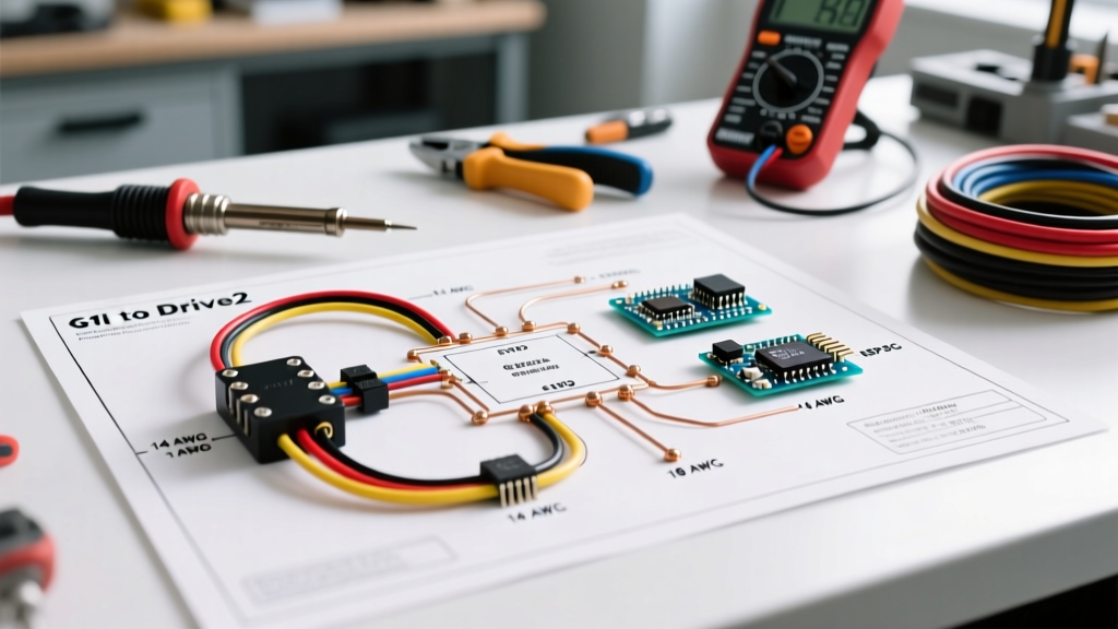
As of 2026, Yamaha's fleet is dominated by the Drive and Drive2 platforms, which utilize advanced 48V AC brushless architectures. However, thousands of legacy G1, G9, and G14 models remain in active service on private estates and commercial courses. Transitioning between these eras requires a fundamental understanding of how Yamaha moved from resistor-based DC speed control to solid-state pulse-width modulation (PWM) and, ultimately, to three-phase AC motor controllers. This comprehensive tutorial breaks down the exact wiring topologies, wire gauge requirements, and diagnostic procedures necessary to safely wire and troubleshoot these iconic vehicles.
Architectural Comparison Matrix: G1 vs. Drive2
Before cutting, stripping, or crimping a single wire, you must identify your specific chassis and controller generation. The wiring diagram for a 1985 Yamaha G1 is fundamentally incompatible with a 2024 Yamaha Drive2. Below is a technical comparison of the core electrical architectures across Yamaha's most prominent generations.
| Feature | Yamaha G1 (1978-1991) | Yamaha G9/G14 (1991-2007) | Yamaha Drive / Drive2 (2007-Present) |
|---|---|---|---|
| System Voltage | 36V (Six 6V Batteries) | 48V (Six 8V Batteries) | 48V (Four 12V or Six 8V) |
| Motor Type | Series-Wound DC Brushed | Series-Wound DC Brushed | AC Brushless Induction |
| Controller | Resistor Coil / Early Solid State | Solid-State DC (e.g., Curtis 1204) | Yamaha G-Drive / Curtis 1236 AC |
| Throttle Input | Inductive Throttle Sensor (ITS) | Inductive Throttle Sensor (ITS) | MCOR (Motor Controller Output Regulator) |
| Main Solenoid | 36V Heavy Duty | 48V Heavy Duty | 48V Albright SW180 or OEM Equivalent |
High-Current Power Circuit: Battery Bank to Motor
The high-current side of the wiring diagram handles the raw amperage required to move a 1,000-pound vehicle plus payload up a 15% grade. In a modern 48V Yamaha Drive2, the power flows from the battery bank to the main solenoid, into the controller's B+ terminal, and out through three heavy-gauge phase wires (U, V, W) to the AC motor.
Wire Gauge Selection and Ampacity Standards
Selecting the correct wire gauge is non-negotiable. According to the NFPA 70 National Electrical Code and SAE J1128 standards for low-tension primary cables, DC systems experience significant voltage drop over distance compared to AC systems. For a 48V golf cart drawing a continuous 300A under load:
- Battery Interconnects: Use minimum 4 AWG stranded copper welding cable. While 6 AWG is sometimes used in OEM budget setups, 4 AWG reduces voltage drop by nearly 40%, extending run-time and preventing terminal melting.
- Main Solenoid to Controller: Use 2 AWG cable. This short run handles the absolute peak surge current during initial acceleration.
- Motor Phase Wires (AC Models): Use 4 AWG flexible silicone or EPDM insulated cable to withstand the high-frequency PWM switching and heat generated near the motor housing.
Pro-Tip: Always use marine-grade adhesive-lined heat shrink on all high-current lugs. Golf carts operate in high-humidity, high-vibration environments where standard electrical tape will eventually unravel and allow copper oxidation.
Low-Current Control Circuit: MCOR and Ignition Logic
The low-current side of the wiring diagram acts as the 'brain' signaling pathway. It operates between 12V and 48V and carries less than 2 amps. Its primary job is to safely engage the high-current solenoid and feed throttle position data to the motor controller.
Understanding the Yamaha MCOR
Older Yamaha carts used an Inductive Throttle Sensor (ITS), which was prone to moisture ingress and mechanical binding. Modern Drive and Drive2 models use the MCOR (Motor Controller Output Regulator). The MCOR is a non-contact, Hall-effect sensor housed in a sealed plastic unit on the accelerator pedal box.
The MCOR typically utilizes a 4-pin connector:
- Pin 1 (Red): 5V Reference from the controller.
- Pin 2 (Black): Sensor Ground.
- Pin 3 (White): Throttle Signal Output (Sweeps from ~0.9V at rest to ~3.3V at full throttle).
- Pin 4 (Green): Redundancy/Safety Check Signal.
Failure Mode Alert: If the controller reads a voltage higher than 1.1V on the signal pin the exact millisecond the key switch is turned on, it will trigger a High Pedal Disable (HPD) error and refuse to engage the solenoid. This is a safety feature to prevent runaway carts.
Step-by-Step Wiring Procedure for a 48V Drive2 Rebuild
When executing a complete harness rebuild or controller swap, follow this strict sequence to prevent short circuits and controller blowouts. Always reference the official Yamaha Golf Car service documentation for your specific serial number range.
- Isolate the Power Source: Disconnect the main negative cable from the battery bank first. Tape the end to prevent accidental contact.
- Wire the Battery Bank: Connect the batteries in series to achieve 48V. Apply anti-oxidant paste to the lead posts before tightening the nuts to exactly 9-11 ft-lbs.
- Install the Main Fuse: Attach a 15A inline fuse to the main positive battery post. This protects the low-current control harness from catastrophic shorts.
- Route High-Current Cables: Connect the positive battery cable to the large terminal on the input side of the main solenoid. Connect the output side of the solenoid to the controller's B+ stud.
- Wire the Solenoid Coil: Connect the small activation terminals on the solenoid. One side receives switched 48V from the key switch (via the forward/reverse microswitches), and the other routes to the controller's solenoid driver output.
- Connect Motor Phases: Attach the U, V, and W phase wires to the controller and motor. Torque these nuts to 12-14 ft-lbs. A loose phase wire will cause an arc flash that will instantly destroy the controller's internal MOSFETs.
- Plug in the Logic Harness: Connect the MCOR, key switch, and brake light switches to the controller's low-current multi-pin plug. Ensure the locking tab clicks securely.
- Reconnect and Test: Reattach the main battery negative. Turn the key on without pressing the pedal. You should hear a distinct, solid 'clack' from the solenoid when you press the pedal, indicating successful logic-to-power handoff.
Diagnostic Troubleshooting & Common Failure Modes
Even with a perfect wiring diagram, component degradation occurs. Here is how to diagnose the three most common Yamaha electrical failures using a digital multimeter (DMM).
- Symptom: Solenoid clicks, but cart does not move.
Diagnosis: High-current side failure. Set your DMM to DC Volts. Place the black probe on the controller B- terminal and the red probe on the controller B+ terminal. Press the pedal. If the voltage reads 48V+ but the cart doesn't move, the solenoid contacts are likely carbon-fouled and failing to pass amperage under load, or the motor brushes (on DC models) are worn past the service limit. - Symptom: No solenoid click, no movement.
Diagnosis: Low-current logic failure. Check the 15A main fuse. Next, verify that the forward/reverse microswitches under the driver's seat are closing properly. These switches are exposed to dirt and water; a blast of compressed air and contact cleaner often resolves the issue. - Symptom: Cart moves in jerky increments or cuts out at high speed.
Diagnosis: Throttle input anomaly. Back-probe the MCOR signal wire. Slowly press the pedal while watching the DMM. The voltage sweep must be perfectly smooth. Any sudden drops to 0V or spikes to 5V indicate a failing internal potentiometer or Hall-effect sensor inside the MCOR unit. Replace the entire MCOR assembly.
CRITICAL SAFETY WARNING: A 48V DC battery bank can sustain a continuous arc flash if shorted. Unlike AC current, DC current does not have a zero-crossing point to naturally extinguish an electrical arc. Always wear ANSI Z87.1 rated safety glasses and insulated gloves when torqueing high-current terminals. Never drop a wrench across the battery terminals.
Final Thoughts on Harness Longevity
Mastering the wiring diagram for Yamaha golf cart systems is about more than just connecting point A to point B; it is about respecting the physics of high-amperage DC electricity. By adhering to strict wire gauge requirements, utilizing marine-grade terminations, and understanding the precise logic thresholds of the MCOR and controller, you can build an electrical system that delivers reliable, tournament-grade performance for years to come. Whether you are restoring a classic 36V G1 or upgrading a modern Drive2 with lithium iron phosphate (LiFePO4) batteries, precision and patience are your most valuable tools.