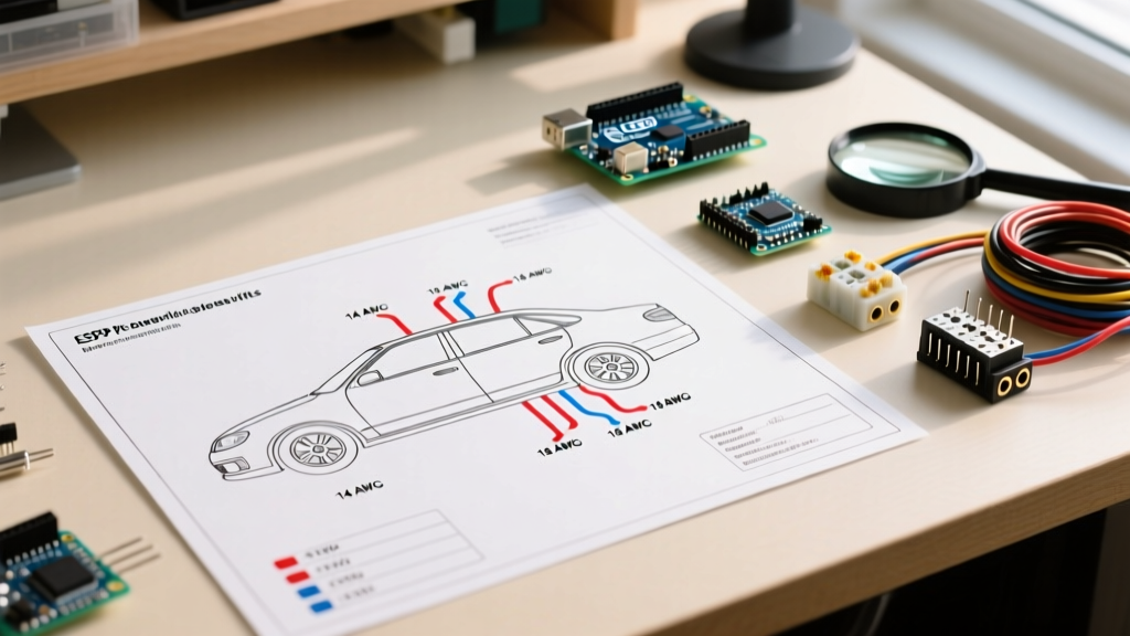

Understanding the Core Wiring Diagram for Car Lights
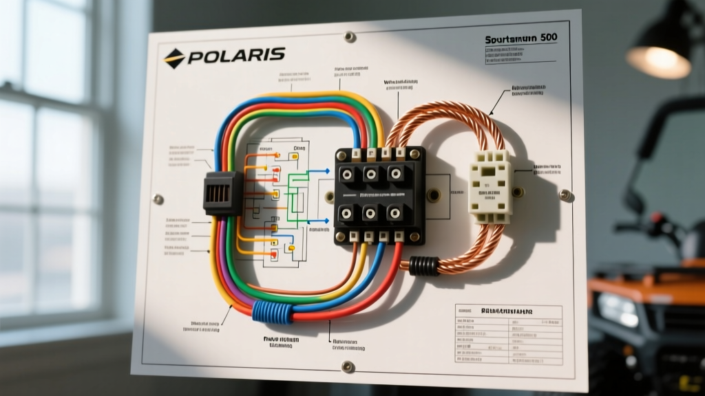
Upgrading or repairing automotive lighting requires more than simply splicing two wires together. Modern vehicles feature complex electrical architectures, and relying on factory headlight switches to drive high-draw halogen bulbs or aftermarket LED arrays often leads to voltage drop, melted switches, and premature component failure. To ensure optimal lumen output and electrical safety, you must implement a dedicated relay harness. This vehicle-specific guide breaks down the universal wiring diagram for car lights, adapting it for both legacy 12V systems and modern 2026 CAN-FD (Controller Area Network Flexible Data-Rate) networks.
The 5-Pin Bosch Relay Architecture
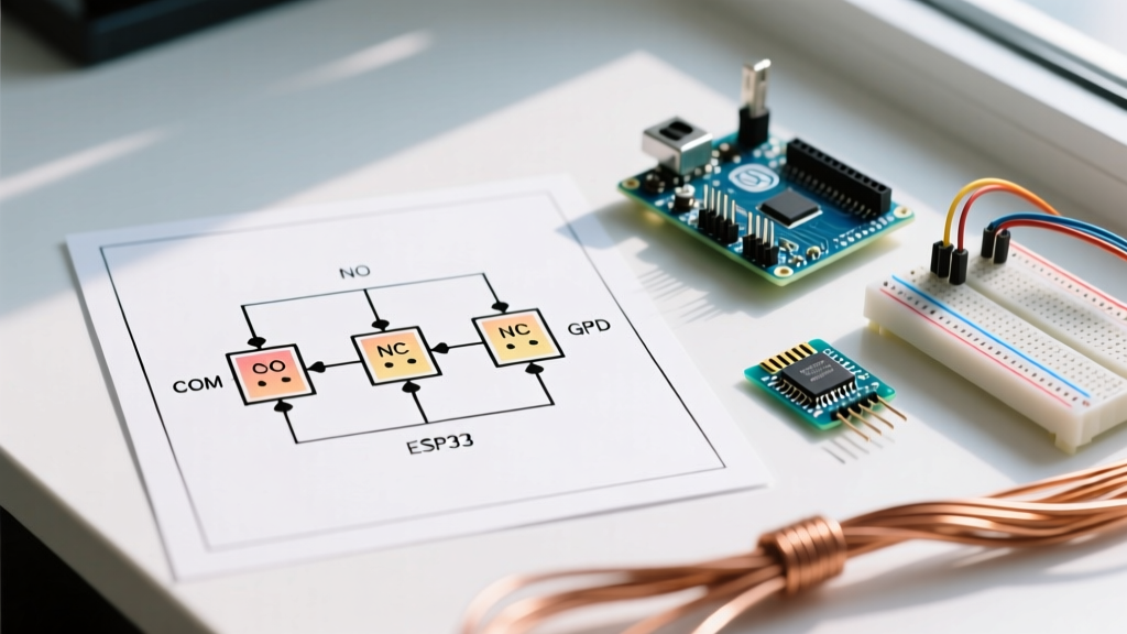
The foundation of any robust automotive lighting diagram is the standard 5-pin ISO mini relay (commonly referenced by the Bosch 0 332 014 150 footprint). While a 4-pin relay works for basic on/off switching, the 5-pin variant includes a Pin 87a (Normally Closed), which is essential for advanced setups like alternating high-beam/low-beam circuits or integrating off-road light bars with factory high beams.
Callout: Why Bypass the Factory Headlight Switch?Factory headlight switches in vehicles built between 2005 and 2018 were typically rated for only 10 to 15 amps. A standard pair of 55W H7 halogen bulbs draws roughly 9.1 amps. As the switch contacts age, resistance increases, generating excess heat. By using a wiring diagram for car lights that incorporates a relay, the factory switch only carries the trigger current (under 0.5 amps), while the heavy current (20+ amps) flows directly from the battery to the bulbs via the relay contacts.
Wire Gauge Selection & Voltage Drop Calculations
Selecting the correct American Wire Gauge (AWG) is critical. Undersized wiring causes voltage drop, which drastically reduces the brightness of halogen filaments and can trigger error codes in LED systems. According to the Engineering Toolbox AWG standards, you must calculate wire length (round-trip distance from battery to light and back to ground) to determine the proper gauge.
| AWG Size | Max Amperage (Chassis) | Recommended Application | Inline Fuse Size |
|---|---|---|---|
| 10 AWG | 30A - 40A | Main power feed from battery to relay (Pin 30) | 30A ATC Blade |
| 12 AWG | 20A - 25A | Relay output (Pin 87) to high-draw halogen/LED pairs | N/A (Protected by main) |
| 14 AWG | 15A | Secondary runs to individual fog lights or DRLs | 10A Mini Fuse |
| 16 AWG | 5A - 8A | Trigger wire from factory headlight plug to Pin 86 | N/A |
| 18 AWG | 3A - 5A | Relay ground (Pin 85) to chassis | N/A |
Vehicle-Specific Adaptations: CAN-Bus and PWM Systems
If you are applying this wiring diagram for car lights to a modern European vehicle (e.g., 2020+ BMW, Audi, or Volkswagen) or a late-model domestic truck, you will encounter Pulse Width Modulation (PWM) and CAN-Bus bulb-check systems. These systems send rapid voltage pulses to the headlight circuit to verify bulb integrity. Because LEDs draw significantly less current than halogens, the vehicle's Body Control Module (BCM) interprets the low draw as a blown bulb, resulting in dashboard error codes, hyper-flashing, or the BCM cutting power entirely.
Load Resistors vs. Active PWM Decoders
To resolve this, your wiring diagram must integrate either passive load resistors or active decoders:
- Passive Load Resistors (50W 6-Ohm): These aluminum-housed resistors ($8-$12 per pair) are wired in parallel with the LED bulb. They simulate the electrical draw of a 55W halogen bulb. Warning: They generate extreme heat (up to 350°F). They must be mounted to a bare metal chassis using stainless steel hose clamps, away from plastic wiring looms and brake lines.
- Active CAN-Bus Decoders: Modules like the GTR Lighting PWM Anti-Flicker or Morimoto H11 CAN-Bus adapters ($40-$65) use internal capacitors and microcontrollers to smooth out PWM signals and simulate the correct impedance without generating excess heat. These are wired in series between the factory plug and your relay trigger wire.
48V Mild-Hybrid and Start-Stop System Considerations
For 2024-2026 vehicles equipped with 48V mild-hybrid systems and aggressive auto start-stop functionality, voltage fluctuations during engine cranking can be severe. When the engine restarts at a stoplight, system voltage can momentarily spike above 15.5V or drop below 9V. If your lighting relay is triggered directly off a switched 12V source that dips during cranking, your headlights will flicker or shut off. To prevent this, wire the relay trigger (Pin 86) through a delay-off timer module or use a dedicated ignition-switched fuse tap (Add-A-Circuit) that remains hot during the 'Crank' position, rather than tapping the headlight switch directly.
Step-by-Step: Routing, Crimping, and Grounding
The physical execution of your wiring diagram for car lights is just as important as the schematic itself. Automotive environments are subjected to extreme vibration, moisture, and thermal cycling.
- Power Feed Routing: Run the 10 AWG main power wire from the battery positive terminal. Install a 30A weatherproof ATC fuse holder within 8 inches of the battery terminal. This is a non-negotiable safety requirement to prevent electrical fires in the event of a short.
- Terminal Crimping: Do not use solder on automotive wiring. Solder wicks into the wire strands, creating a rigid point that will eventually snap under engine bay vibration. Instead, use adhesive-lined marine-grade heat shrink crimp terminals (e.g., Ancor or Tinned Copper). The heat-activated glue seals out moisture, preventing green corrosion (copper oxide) inside the crimp barrel.
- Chassis Grounding: A poor ground causes 90% of automotive lighting issues. Do not simply bolt a ring terminal over painted steel or aluminum. Use a wire brush or 80-grit sandpaper to expose bare metal. Apply the ring terminal, torque it to factory specifications, and coat the exposed metal with Permatex 22058 Dielectric Grease to prevent galvanic corrosion.
Expert Troubleshooting Tip: If your newly wired LED light bar flickers only when the engine is running, you are likely picking up alternator whine (EMI/RFI interference). Reroute the 12V power cable away from the alternator and ignition coils, or install a 12V inline noise filter (capacitor choke) near the relay.
Troubleshooting Common Lighting Failures
Even with a perfect wiring diagram for car lights, real-world variables can introduce faults. Use a digital multimeter (DMM) to diagnose these common failure modes:
Multimeter Testing Points
- Relay Pin 30 (Battery Feed): Should read 12.4V - 12.6V at all times. If it reads 0V, check the inline fuse and battery terminal connection.
- Relay Pin 86 (Trigger): Should read 12V when the factory headlights are turned on. If it reads 6V-8V, you are experiencing voltage drop in the factory headlight switch, or you are dealing with a PWM signal. An oscilloscope or a DMM with a 'Min/Max' and 'Duty Cycle' function is required to verify PWM frequency.
- Relay Pin 87 (Load Output): Should read within 0.2V of Pin 30 when the relay is engaged. If Pin 30 reads 12.5V but Pin 87 reads 10.5V, the internal relay contacts are pitted or failing. Replace the relay immediately.
- Ground Circuit: Set your DMM to measure resistance (Ohms). Place one probe on the light housing ground and the other on the battery negative terminal. It should read less than 0.5 Ohms. Anything higher indicates a corroded or loose ground strap.
Compliance and Safety Standards
When modifying exterior lighting, especially when adding auxiliary driving lights or upgrading headlight housings, you must remain compliant with federal regulations. According to the National Highway Traffic Safety Administration (NHTSA) FMVSS 108 guidelines, aftermarket lighting must not exceed specific candela limits and must maintain proper beam cutoff patterns to prevent blinding oncoming traffic. Always ensure your relay harness includes a cabin-mounted toggle switch with an LED indicator for auxiliary off-road lights, allowing you to completely isolate them from the factory headlight circuit when driving on public roads.
By following this comprehensive wiring diagram for car lights, utilizing the correct AWG sizing, and respecting modern CAN-Bus architectures, you will achieve a lighting setup that is not only exceptionally bright but electrically bulletproof for the lifespan of your vehicle.