
Understanding the 240v Electric Water Heater Wiring Diagram
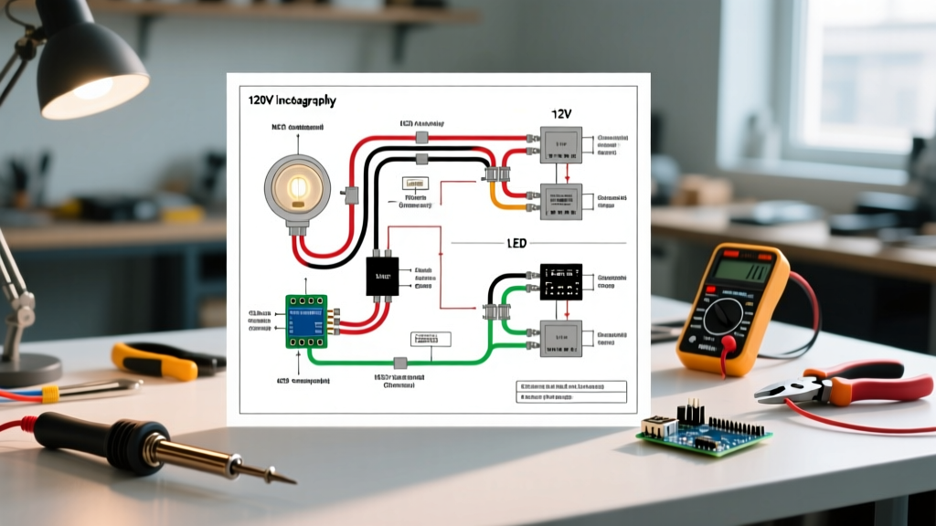
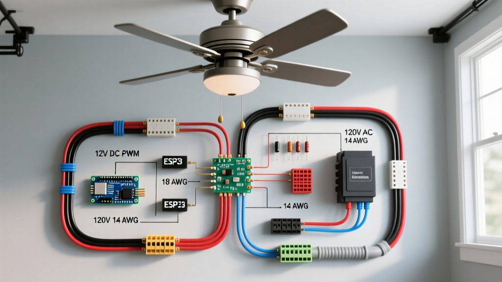
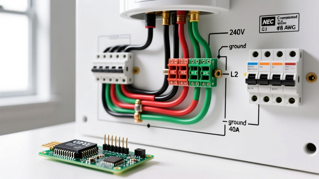
Wiring a standard residential storage tank water heater requires a dedicated 240-volt circuit. Unlike 120V appliances or 240V electric ranges, a standard 4500-watt electric water heater does not require a neutral wire. The 240v electric water heater wiring diagram relies entirely on two ungrounded (hot) conductors and an equipment grounding conductor. This pure 240V setup powers the upper and lower heating elements sequentially, managed by the upper and lower thermostats.
A common and dangerous mistake made by novice DIYers is attempting to use the white neutral wire in a 10/2 NM-B cable as a current-carrying hot leg without properly re-identifying it. According to the National Electrical Code (NEC), if a white wire is used as an ungrounded conductor, it must be permanently re-identified with black or red electrical tape or paint at every termination point. Failing to do so creates a severe shock hazard for future technicians working on the panel.
NEC Breaker Sizing & The 125% Continuous Load Rule
Water heaters are classified as continuous loads under NEC Article 422.13. This means the branch circuit must be rated at no less than 125% of the appliance's nameplate rating. For the most common residential water heater configuration—a 50-gallon tank with 4500-watt elements—the math dictates your breaker and wire size.
NEC Article 422.13 Storage-Type Water Heaters: Branch-circuit conductors supplying household storage-type water heaters that have a capacity of 120 gallons or less shall have an ampacity not less than 125 percent of the nameplate rating.
Let us break down the calculation for a standard 4500W unit:
- Base Amperage: 4500 Watts / 240 Volts = 18.75 Amps.
- 125% Multiplier: 18.75 Amps x 1.25 = 23.44 Amps.
- Breaker Selection: The next standard breaker size above 23.44A is 25A. However, 25A double-pole breakers are specialty items and rarely stocked. The NEC permits the next standard size up, which is a 30-Amp double-pole breaker.
Wire Gauge & Breaker Sizing Matrix
Selecting the correct wire gauge is critical to prevent voltage drop and melted lugs. The table below outlines the requirements for standard resistive electric water heaters based on 2026 copper pricing and NEC ampacity tables (Table 310.16).
| Element Wattage | Voltage | Base Amps | 125% NEC Calc | Breaker Size | Min. Copper Wire (NM-B / THHN) |
|---|---|---|---|---|---|
| 3000W | 240V | 12.5A | 15.6A | 20A Double-Pole | 12 AWG |
| 3800W | 240V | 15.8A | 19.7A | 25A or 30A Double-Pole | 10 AWG |
| 4500W | 240V | 18.75A | 23.4A | 30A Double-Pole | 10 AWG |
| 5500W | 240V | 22.9A | 28.6A | 30A or 40A Double-Pole | 8 AWG (for 40A) |
Step-by-Step Panel to Heater Wiring Flow
Follow this precise sequence to ensure a safe, code-compliant installation. Always verify local amendments, as some jurisdictions adopting the latest NEC cycles require Ground Fault Circuit Interrupter (GFCI) protection for water heaters located in unfinished basements or crawlspaces.
1. Panel Preparation & Breaker Installation
- De-energize the Panel: Turn off the main service disconnect. Use a non-contact voltage tester and a digital multimeter to verify the bus bars are dead.
- Seat the Breaker: For a standard Square D Homeline panel, snap a HOM230 (30A double-pole) onto the bus bar stabs. Ensure it seats firmly. If your local code requires GFCI protection, you will need a specialized breaker like the HOM230GFI, which costs approximately $55 compared to the $12 standard breaker.
- Terminate the Hots: Strip 5/8 inch of insulation from the black and red (or re-identified white) 10 AWG conductors. Torque the breaker terminal screws to the manufacturer's specification—typically 35 in-lbs for Square D and Eaton breakers. Use a calibrated torque screwdriver to prevent loose connections that lead to arcing.
2. Routing the Cable & Grounding
Run 10/2 NM-B cable (commonly known as Romex) from the panel to the water heater junction box. Secure the cable with metal or UV-resistant plastic staples within 8 inches of the panel and every 4.5 feet thereafter. At the panel, terminate the bare copper ground wire onto the equipment grounding bus bar. Never land the ground wire on the neutral bus bar in a main lug subpanel.
3. Water Heater Junction Box Termination
At the water heater, route the cable through a 3/4-inch NM-B connector into the 4x4 metal junction box mounted on the heater's top plate. Connect the two hot wires to the appliance pigtail using wire nuts. For 10 AWG solid wire, standard wire nuts often fail to grip securely. Use IDEAL Wing-Nut 454 or WAGO 221 lever nuts (rated for 10 AWG) to ensure a vibration-proof, high-tension connection. Connect the bare ground to the green ground screw inside the junction box and the heater's ground lug.
Thermostat Sequencing: How the 240V Diagram Actually Works
Understanding the internal wiring diagram of the water heater is crucial for troubleshooting. A 4500W dual-element water heater does not run both elements simultaneously. Doing so would draw 37.5 Amps, instantly tripping a 30A breaker. Instead, the system uses a sequential interlock:
- Cold Start: When the tank is full of cold water, 240V is routed to the upper thermostat. The upper element heats the top third of the tank, providing immediate lukewarm water to the fixtures.
- Handoff: Once the upper thermostat is satisfied, it acts as a transfer switch. It cuts power to the upper element and routes 240V down to the lower thermostat.
- Recovery: The lower element heats the remaining volume of the tank. If a massive hot water draw occurs, the lower thermostat drops out, and priority returns to the upper thermostat.
If your water heater is tripping the breaker immediately upon energizing, one of the elements has likely shorted to ground, or the dry-fire protection limit switch on the upper thermostat has failed closed.
Common Panel Failure Modes & Troubleshooting
Even with a perfect 240v electric water heater wiring diagram execution, environmental and mechanical factors can cause failures. Here are the most common edge cases we see in the field:
Melted Breaker Lugs & Bus Bar Damage
If the 10 AWG wire was not stripped to the exact 5/8-inch depth, or if the terminal screw was not torqued to 35 in-lbs, the connection will exhibit high resistance. Over months of 18.75A continuous draw, this resistance generates intense heat, melting the breaker casing and scorching the panel bus bar. Fix: Replace the breaker immediately. If the bus bar stab is pitted or discolored, the entire panel may require replacement or the breaker must be moved to a pristine, unused stab.
Nuisance Tripping in High-Efficiency Hybrids
If you are upgrading from a standard resistive heater to a Heat Pump Water Heater (HPWH) like the Rheem ProTerra series, the wiring diagram changes slightly. While the compressor and fans run on 120V (derived from a split-phase 240V setup using a neutral), the backup resistive elements still require 240V. Many HPWHs require a 30A or even 40A circuit depending on the backup element size. Always verify the specific nameplate of the hybrid unit, as assuming a standard 30A 10/2 wiring diagram will result in immediate failure and voided warranties.
Additional Resources & Code Compliance
Electrical codes evolve to prioritize life safety. Always consult the latest editions of the NEC and local building authority guidelines before beginning any panel work. For comprehensive data on water heating efficiency and electrical load management, refer to the U.S. Department of Energy's Water Heating Guide. To review the exact text regarding branch circuit sizing and continuous load calculations, access the NFPA 70 National Electrical Code documentation. Finally, for specific product specifications and internal wiring schematics, consult the EPA WaterSense program and your manufacturer's installation manual.