
Decoding the Schematic: ABYC E-11 Standards and Color Codes
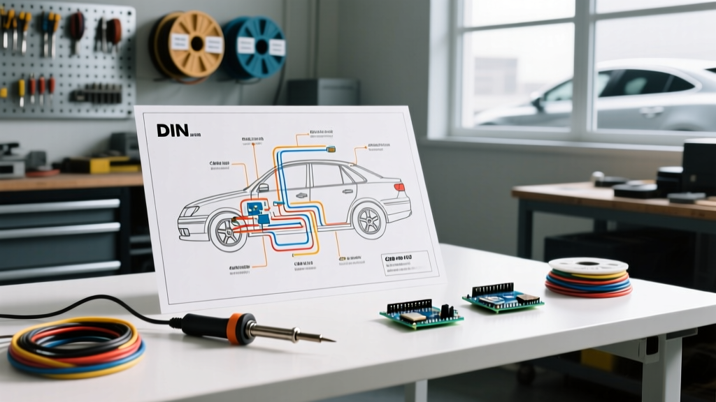
Marine environments present a uniquely hostile operating theater for electrical systems. Unlike automotive applications, boat electrical systems must withstand constant vibration, high humidity, and corrosive saltwater exposure. When planning a vessel refit or troubleshooting an existing fault, accurately reading a marine electrical wiring diagram is the critical first step. In North America, these diagrams are governed by the ABYC E-11 (AC & DC Electrical Systems on Boats) standard, which dictates specific wire color codes, overcurrent protection placement, and voltage drop limits that differ significantly from standard automotive or residential wiring.
A common mistake made by DIY boaters is assuming marine DC color codes match automotive ones. In a marine wiring diagram, black wire is never a positive hot lead; it is strictly reserved for the DC negative return. Misinterpreting this on a schematic can lead to catastrophic short circuits or equipment damage.
Standard ABYC DC Wire Color Codes
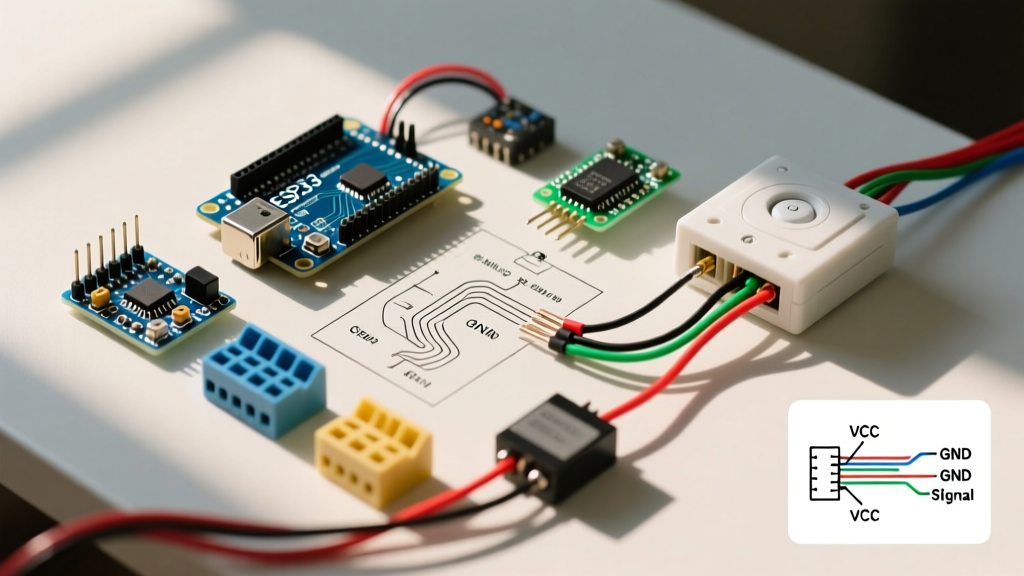
| Wire Color | Function / Application | Diagram Symbol / Label |
|---|---|---|
| Red | DC Positive (Main Battery Feed) | B+ / POS |
| Yellow | DC Positive (Secondary / Distribution) | SW / FUSED |
| Black or Yellow/Black Stripe | DC Negative (Return to Busbar) | B- / NEG |
| Green or Green/Yellow Stripe | DC Grounding / Bonding System | GND / BOND |
| Yellow/Red Stripe | Engine Starting Circuit (Ignition) | IGN / START |
Core Architecture: Busbars, Shunts, and Distribution
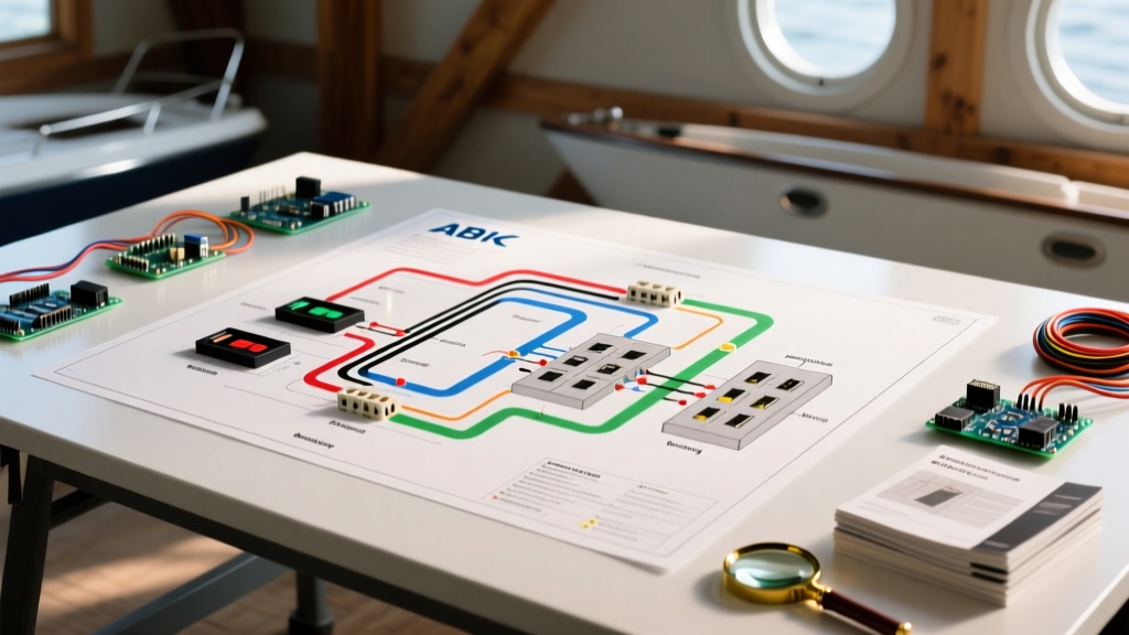
A professional marine electrical wiring diagram will rarely show wires daisy-chained directly from the battery to the load. Instead, modern marine schematics utilize a centralized distribution architecture centered around busbars and shunts.
The Negative Busbar and Shunt Placement
When tracing the negative return path on your diagram, look for the DC shunt. The shunt is a precision resistor (typically 500A/50mV) used by battery monitors to calculate state-of-charge. Critical Rule: The wiring diagram must show all DC negative loads returning to the load side of the shunt. If a bilge pump or chart plotter negative wire bypasses the shunt and goes directly to the battery terminal, the battery monitor will not track that draw, leading to inaccurate state-of-charge readings and potential deep-discharge damage to expensive lithium banks.
Overcurrent Protection Mapping
ABYC standards require overcurrent protection (fuses or circuit breakers) to be placed within 7 inches of the power source, or up to 72 inches if the wire is enclosed in a continuous sheath. On your wiring diagram, look for the fuse symbols immediately adjacent to the positive battery terminal or main positive busbar. For high-amperage main feeds (e.g., 250A+ inverter feeds), diagrams will specify Class T or ANL fuses, such as the Blue Sea Systems 5502 ANL Fuse Block (retailing around $45). For branch circuits, the diagram will route the yellow positive wire into a distribution block like the Blue Sea ST Blade Fuse Block (Part # 5025), which typically costs between $45 and $55 depending on the circuit count.
Tracing the Circuit: Voltage Drop and Wire Sizing
Reading the wire gauge annotations on a marine electrical wiring diagram requires an understanding of voltage drop. According to Blue Sea Systems' ampacity guidelines, wire must be sized not just for the maximum current (ampacity), but for the allowable voltage drop over the total round-trip length of the circuit.
Pro-Tip: The 3% vs. 10% Rule
Marine diagrams should annotate critical electronics (VHF radios, radar, GPS chartplotters like the Garmin GPSMAP 8600 series) with a 3% maximum voltage drop limit. Non-critical loads (cabin lights, baitwell pumps) can be sized for a 10% drop. If your diagram shows 10 AWG wire for a 15A chart plotter run that is 30 feet away, the wire is undersized; the schematic should be revised to 8 AWG or 6 AWG to prevent the plotter from rebooting when the VHF transmits.
Step-by-Step Diagnostic Flow Using the Diagram
- Identify the Source: Locate the specific battery bank (House vs. Start) and the main positive busbar on the schematic.
- Locate the Overcurrent Device: Find the specific fuse or breaker rating protecting the branch. Verify it matches the physical panel on the vessel.
- Trace the Positive Lead: Follow the yellow (or red) wire through any relays, switches, or solenoids. Note the wire gauge and color-code stripe markers.
- Identify the Load: Confirm the load type. If it is an inductive load (e.g., a windlass motor), check the diagram for a flyback diode or suppression capacitor to protect upstream switches.
- Trace the Negative Return: Follow the black wire back to the specific negative busbar, ensuring it passes through the DC shunt.
Common Edge Cases and Failure Modes in Marine Wiring
Even a perfectly drafted marine electrical wiring diagram can fail if the physical execution ignores marine-specific edge cases. When auditing a vessel's wiring against its schematic, watch for these common failure modes:
1. The 'Ghost' Voltage Drop from Corroded Crimps
A schematic assumes zero resistance at connection points. In reality, salt air wicks into unsealed crimps, creating copper oxide—a highly resistive semiconductor. This causes a 'ghost' voltage drop that won't show up on a simple continuity test but will severely degrade performance under load. Solution: All crimps must use adhesive-lined, marine-grade heat shrink tubing, such as 3M MFP-301. The diagram should explicitly note 'Adhesive-Lined Heat Shrink Required' at all bilge and engine room termination points.
2. Alternator Field Wire Disconnects with Lithium Upgrades
Many older wiring diagrams show the alternator's internal regulator wired directly to the battery. When owners upgrade to Lithium Iron Phosphate (LiFePO4) banks, the Battery Management System (BMS) may disconnect the battery if a cell reaches high voltage. If the alternator is still connected, the sudden loss of the battery bank causes a voltage spike that will instantly destroy the alternator diodes and fry sensitive electronics. Modernized diagrams for lithium refits must include an Alternator Protection Device (APD) or an external regulator (like the Victron Orion or Wakespeed WS500) with a dedicated alternator disconnect relay controlled by the BMS.
Essential 2026 Tooling for Marine Refits
Executing the physical build based on your marine electrical wiring diagram requires specialized tooling. Standard automotive crimpers will not achieve the gas-tight, pull-tested connections required for marine environments.
- Wire Crimping: The Knipex 97 53 14 ratcheting crimping tool (approx. $110) is the industry standard for insulated marine terminals. It ensures a uniform, calibrated crimp force every time, preventing the wire from pulling out under engine vibration.
- Wire Stripping: The Klein Tools 11063W wire stripper prevents nicking the fine-strand tinned copper found in marine wire (like Ancor Marine Grade). Nicked strands reduce ampacity and create hot spots.
- Testing: A high-impedance digital multimeter like the Fluke 87V MAX (approx. $500) is mandatory for diagnosing parasitic draws and accurately measuring the millivolt drops across busbar connections and shunts.
- Wire Selection: Always use Type III, 105°C rated, tinned copper marine wire. As noted in West Marine's wiring advisory, the tinning prevents black corrosion from creeping under the insulation, a common failure point in standard bare-copper THHN wire.
Frequently Asked Questions
Do I need a separate wiring diagram for AC and DC systems?
Yes. ABYC standards require AC (shore power, inverter output, generator) and DC (battery, alternator, solar) systems to be physically separated and documented on distinct schematics. Mixing AC and DC on the same diagram—or worse, in the same conduit or junction box—creates severe shock hazards and violates marine insurance requirements.
How do I represent a solar charge controller on a marine diagram?
A solar charge controller (e.g., Victron SmartSolar MPPT 150/35) should be drawn between the solar array and the house battery busbars. The diagram must show a dedicated DC breaker on the battery side (to protect against reverse current faults) and a separate PV disconnect or breaker on the solar array side. Always connect the battery side first, and disconnect the battery side last, as noted in manufacturer schematics.