
Pre-Installation Audit: Planning Your 36V Club Car Rebuild
Restoring or upgrading a vintage 36V Club Car DS (specifically the 1981–1995 resistor/coil or early solid-state models) requires meticulous electrical planning. Unlike modern 48V or 72V platforms, the 36-volt architecture relies on high amperage to deliver torque, meaning your wiring integrity is the single most critical factor in preventing voltage drop and thermal runaway. When referencing an electric 36V Club Car wiring diagram, DIYers often overlook the control circuit logic, focusing solely on the main battery bank. This installation planning guide bridges that gap, providing exact component specifications, wire gauge requirements, and edge-case troubleshooting for 2026 restorations.
Expert Note: Never mix battery ages or chemistries in a 36V series bank. A single degraded 6V cell will act as a resistor, dragging down the entire 36-volt system and causing premature failure of the remaining five batteries.
2026 Component Bill of Materials (BOM) & Sourcing
Before pulling a single wire, verify your component manifest. Pricing below reflects early 2026 market rates for premium, cart-rated electrical parts.
| Component | Specification / Part Number | Estimated 2026 Cost | Installation Notes |
|---|---|---|---|
| Battery Bank | 6x Trojan T-105 6V Deep Cycle (225Ah) | $1,450 - $1,600 | Requires 110 in-lbs torque on lead posts. |
| Main Cables | 6 AWG Welding Cable (Red/Black) | $4.50 / ft | Must use 3/8" heat-shrink ring terminals. |
| Solenoid | 36V Heavy Duty (OEM #1012886 or Albright SW180) | $55 - $85 | Must include 270-ohm precharge resistor. |
| Controller | Curtis 1204 or 1205 PWM (Upgrade from V-Glide) | $280 - $340 | Requires 0-5k ohm throttle input signal. |
| F&R Switch | 6-Terminal Mechanical Forward/Reverse | $65 - $90 | Lubricate internal contacts with dielectric grease. |
The Main Power Loop: Routing the 6 AWG Battery Cables
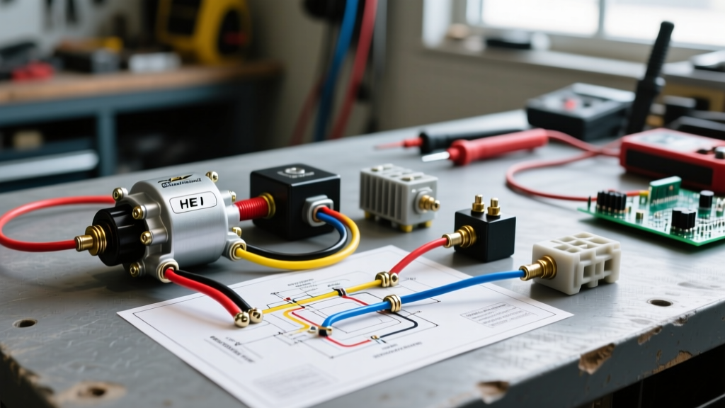
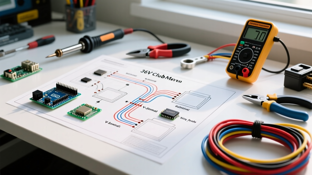
The foundation of any 36 volt Club Car wiring diagram is the main power loop. Your cart operates on a series circuit comprising six 6V batteries. The negative terminal of Battery 1 connects to the positive of Battery 2, continuing through Battery 6. The final positive terminal routes to the solenoid, while the final negative routes to the motor controller's B- terminal.
Wire Gauge and Lug Crimping Standards
For a 36V system pulling upwards of 300 amps under heavy load or hill climbs, 6 AWG wire is the absolute minimum. However, the wire is only as good as its terminations. In 2026, we strongly recommend abandoning standard mechanical crimpers in favor of hex-crimp hydraulic tools for your 6 AWG lugs. A poorly crimped lug will introduce micro-ohms of resistance, generating immense heat. According to safety guidelines published by the Battery Council International, high-resistance connections are the leading cause of DC electrical fires in golf carts.
- Cable Length: Measure twice, cut once. Keep interconnect cables as short as physically possible (usually 12 to 18 inches) to minimize voltage drop.
- Terminal Prep: Use a stainless-steel wire brush on battery posts before installation. Apply a thin layer of NO-OX-ID A-Special conductive grease, not standard petroleum jelly, which can act as an insulator if applied too thickly.
- Torque Specification: Trojan Battery explicitly mandates 110 inch-pounds (not foot-pounds) for their T-105 series. Over-torquing will crack the soft lead post, causing acid creep and terminal corrosion.
Control Circuit Logic: Solenoid Activation and Microswitches
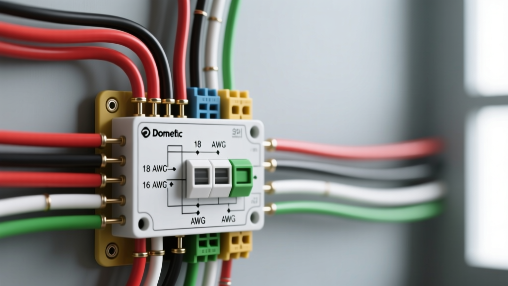
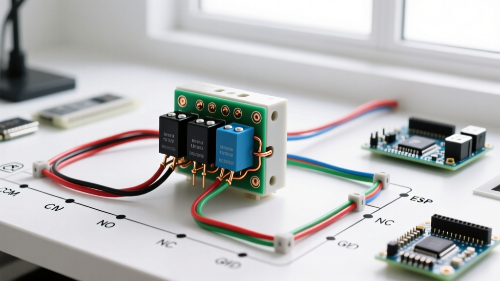
While the 6 AWG cables carry the heavy current, the 12 AWG control circuit acts as the brain of your electric 36V Club Car. The solenoid is a heavy-duty relay that connects the battery bank to the motor controller. It features two large terminals (main power) and two small terminals (the activation coil).
The Precharge Resistor: A Critical Edge Case
The most common failure mode in 36V Club Car restorations is solenoid contact welding. When the solenoid engages, the massive inrush current required to charge the motor controller's internal capacitors can arc across the small gap of the solenoid contacts, melting them together. If this happens, the cart will not stop when you release the pedal.
The Fix: You must install a 270-ohm, 5-watt precharge resistor across the two large terminals of the solenoid. This resistor allows a tiny trickle of current to pre-charge the controller's capacitors before the main solenoid contacts close, eliminating the inrush arc. This is a mandatory inclusion in any modernized 36 volt wiring schematic.
Throttle Input: V-Glide vs. Solid State PWM
Vintage 1981–1994 models utilized a V-Glide, a mechanical variable resistor that physically restricted current. These are notorious for wearing out, causing erratic speed control and overheating. If your wiring diagram features a V-Glide, the best practice in 2026 is to bypass it entirely and install a solid-state PWM controller like the Curtis 1204 or 1205 series. This requires replacing the V-Glide with a 0-5k ohm inductive throttle sensor (ITS) mounted directly to the accelerator pedal box, feeding a clean analog signal to the Curtis controller's J1/J2 pins.
Troubleshooting Matrix: Common 36V Failure Modes
Even with a perfect wiring diagram installation, environmental factors and component fatigue can cause issues. Use this diagnostic matrix to isolate faults without guessing.
| Symptom | Probable Cause | Diagnostic Step & Solution |
|---|---|---|
| Solenoid clicks, but cart won't move. | F&R Switch failure or motor brush wear. | Check for 36V at the motor controller's M- terminal when pedal is pressed. If missing, rebuild the 6-terminal F&R switch. |
| Cart runs for 5 minutes then dies. | Voltage drop across a corroded battery interconnect. | Use a multimeter to test voltage drop across each cable while under load. Any reading over 0.1V indicates a bad crimp or corroded post. |
| Solenoid stays engaged after releasing pedal. | Welded contacts due to missing precharge resistor. | Disconnect main battery negative immediately. Replace solenoid and install a 270-ohm 5W precharge resistor. |
| Erratic jerking during acceleration. | Failing throttle sensor (ITS) or worn microswitch. | Measure resistance across the ITS signal wires while slowly pressing the pedal. The sweep should be smooth, not jumpy. |
Safety Protocols and Final Commissioning
Before applying power for the first time, elevate the rear wheels off the ground using heavy-duty jack stands. Never perform initial commissioning with the tires on the pavement; a wiring error could result in an uncontrollable runaway cart. According to maintenance protocols outlined by Trojan Battery, always ensure the battery bank is fully charged and properly watered with distilled water prior to the first load test.
Step-by-Step Commissioning Flow
- Visual Inspection: Verify all 6 AWG cables follow the series routing diagram. Ensure no positive and negative cables cross or touch without insulation.
- Control Circuit Test: With the main battery pack disconnected, apply 12V from a separate battery charger to the solenoid's small terminals. You should hear a definitive, loud 'clack'.
- Low-Speed Test: Connect the main pack. Turn the key to ON, select Forward, and gently press the pedal. The cart should accelerate smoothly on the stands.
- Thermal Scan: After 10 minutes of running on the stands, use an infrared thermometer to scan all battery lugs and the solenoid terminals. Temperatures should not exceed ambient + 15°F.
Frequently Asked Questions (FAQ)
Can I use 4 AWG wire instead of 6 AWG for my 36V Club Car?
Yes, 4 AWG is an excellent upgrade, especially if you plan to increase the motor's amperage draw or add high-wattage accessories. It reduces voltage drop and runs cooler, though it is slightly more difficult to route in the tight battery trays of the DS platform.
Why does my 36V cart seem slower than my neighbor's 48V cart?
Power (Watts) equals Volts times Amps. A 36V system must pull significantly more amps to produce the same horsepower as a 48V system. While 36V provides excellent low-end torque, it hits a voltage ceiling at higher RPMs. If top speed is your priority, consider a 48V conversion kit, which requires swapping the charger, solenoid, and controller.
Do I need to disconnect the batteries when welding on the cart frame?
Absolutely. The voltage spikes induced by arc welding can instantly destroy the sensitive MOSFETs inside your Curtis motor controller and fry the solenoid coil. Always disconnect the main negative cable and isolate the battery bank before any chassis welding.