
Introduction to Suburban RV Water Heater Electrical Systems
Understanding the wiring diagram for Suburban RV water heater models—specifically the widely used SW6DE (6-gallon) and SW10DE (10-gallon)—requires a dual-system approach. Unlike standard residential units, these RV appliances operate on a hybrid electrical architecture: a 12V DC system for the control board, direct spark ignition (DSI), and the combustion blower motor, alongside a 120V AC system for the auxiliary electric heating element. As of 2026, with the rising integration of lithium house batteries and advanced inverter-chargers in RVs, ensuring precise voltage delivery and correct wire gauge sizing is more critical than ever to prevent control board burnout and motor stalling.
This motor wiring tutorial and comprehensive reference guide will break down the exact terminal routings, wire gauge requirements, and advanced troubleshooting techniques for the Suburban 521039 control board (the current 2026 standard replacement for the legacy 232718 board).
Core Components & Control Board Architecture
Before tracing the wires, you must identify the primary electrical nodes. The Suburban DE series relies on a centralized printed circuit board (PCB) to manage both AC and DC loads safely.
- Control Board (Part #521039): The brain of the operation. It monitors the thermostat loop, fires the igniter, drives the 12V blower motor, and manages the 120V AC relay. Retail pricing in 2026 averages between $95 and $125.
- 12V DC Blower Motor: A brushed DC squirrel-cage fan that draws between 3.5A and 4.5A. It purges the combustion chamber before ignition and supplies oxygen during the burn cycle.
- Sail Switch: A pneumatic microswitch wired in series with the thermostat. It proves that the blower motor is moving sufficient air before the board opens the gas valve.
- Thermostat (T-Stat) & Emergency Cut-Off (ECO): 12V DC safety loops that interrupt the ground path if the water reaches 180°F (ECO) or the user turns off the interior switch (T-Stat).
- 120V AC Heating Element: A 1,440-watt resistive load that draws exactly 12 amps on a standard 15-amp RV branch circuit.
The Complete Wiring Diagram for Suburban RV Water Heater
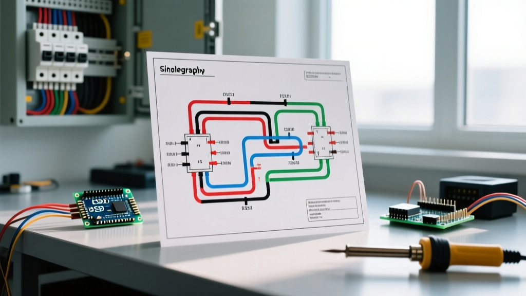
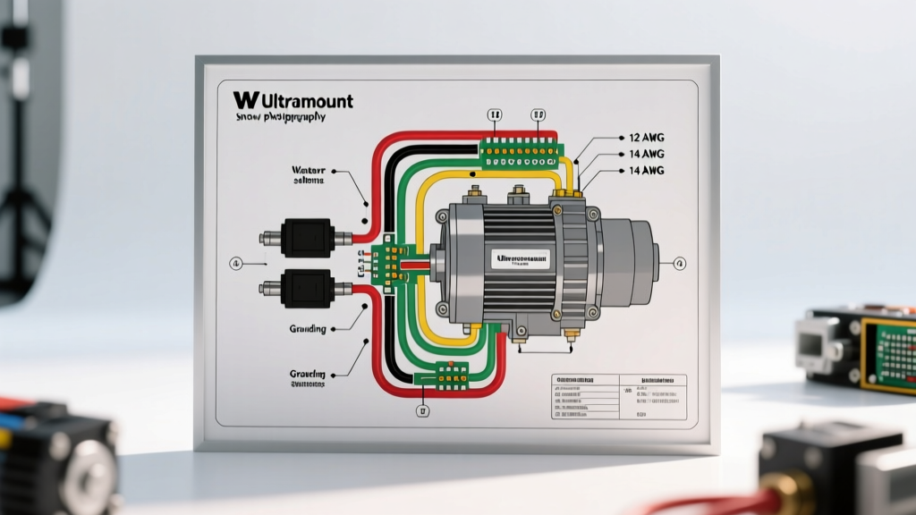
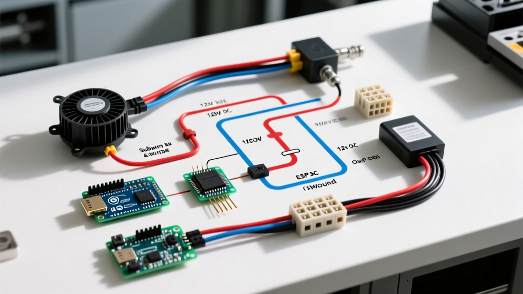
Below is the functional wiring flow for the modern Suburban 521039 control board. The board utilizes distinct terminal blocks to separate high-voltage AC and low-voltage DC, preventing cross-contamination and EMI interference.
12V DC Ignition and Blower Motor Circuit
The 12V side is where most wiring failures occur. The control board requires a clean, stable 12V DC input to operate the internal logic gates and drive the blower motor.
- Main 12V Power: A 12 AWG red wire routes from the RV's 12V fuse panel (protected by a 10A or 15A fuse) to the +12VDC IN terminal on the board. A 12 AWG black wire routes from the GND terminal directly to the RV chassis ground or negative busbar.
- Thermostat & ECO Loop: The board sends a low-current 12V signal out to the interior T-Stat switch, which daisy-chains to the ECO switch on the tank, and returns to the board's T-STAT/ECO RETURN terminal. If either switch opens, the board kills the motor and gas valve.
- Blower Motor Routing: The board's internal relay switches the 12V ground to the motor. Two wires (typically orange and white) run from the MOTOR terminal block to the blower motor spade connectors.
Motor Wiring Pro-Tip: While brushed DC motors will technically spin if polarity is reversed, the Suburban blower fan blade is pitched to push air in a specific direction. If you swap the orange and white wires during a motor replacement, the fan will pull air away from the combustion chamber, failing to generate the positive pressure required to close the sail switch. Always match the factory wire colors or verify airflow direction before sealing the access panel.
120V AC Heating Element Circuit
The 120V AC side operates entirely independently of the 12V DSI system, though both are managed by the same physical board.
- AC Input: A 14 AWG black (hot) and white (neutral) wire pair enters the 120V AC IN block from the RV's AC breaker panel (15A or 20A breaker).
- Element Output: The board's internal AC relay switches the hot leg. A 14 AWG black wire exits the ELEMENT terminal and routes to the 120V heating element mounted on the tank flange. The neutral wire bypasses the board and wires directly to the element's second terminal.
- High-Limit Switch (AC): The hot wire must pass through the 120V high-limit thermal cutoff switch (set to 180°F) before reaching the element. If the tank overheats on electric mode, this switch physically breaks the AC circuit.
Wire Gauge Selection & Voltage Drop Matrix
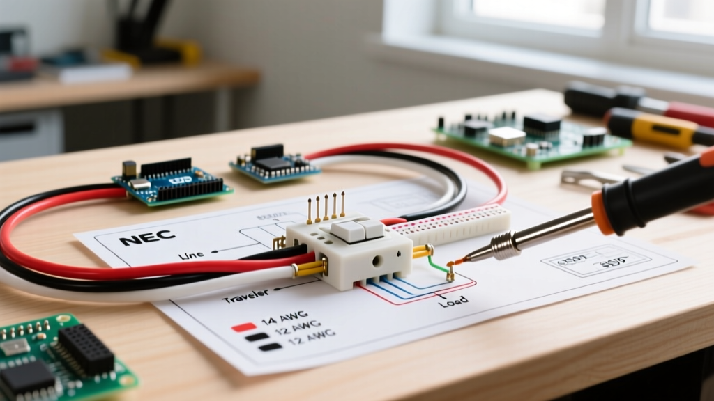
Undersized wiring is the number one cause of Suburban water heater failure in older RVs. The 12V DC blower motor requires a minimum of 10.5V at the spade connectors to spin fast enough to close the sail switch. If you use 16 AWG wire for a 15-foot run, voltage drop will starve the motor. Refer to the matrix below, aligned with National Electrical Code (NEC) NFPA 70 standards for DC low-voltage routing.
| Circuit Type | Max Amperage | Run Length (One Way) | Minimum Wire Gauge (AWG) | Breaker / Fuse Size |
|---|---|---|---|---|
| 12V DC Main Power | 10A (Peak) | Up to 10 ft | 14 AWG | 15A Automotive Fuse |
| 12V DC Main Power | 10A (Peak) | 10 ft to 20 ft | 12 AWG | 15A Automotive Fuse |
| 12V T-Stat / ECO Loop | < 0.5A | Any | 18 AWG | N/A (Protected by Main) |
| 120V AC Element Input | 12A (Continuous) | Up to 30 ft | 14 AWG | 15A AC Breaker |
Advanced Motor Troubleshooting: The Sail Switch Stall
When approaching the wiring diagram for Suburban RV water heater systems from a motor-diagnostic perspective, the most common edge case is the 'Sail Switch Stall'. The control board LED will flash 3 times, pause, and repeat. This indicates the board turned on the blower motor, but the sail switch never closed.
Step-by-Step Diagnostic Flow
- Measure Voltage Under Load: Do not measure voltage with the motor disconnected. Back-probe the motor spade connectors while the board is attempting to start the fan. If you read 12.6V but the motor doesn't spin, the motor brushes are dead (replace motor, Part #232718 or equivalent 2026 update). If you read 9.5V or lower, you have a voltage drop issue in the wiring harness.
- Inspect the Sail Switch Paddle: The physical paddle on the sail switch can warp from high heat. If the motor is spinning at full RPM (verified by a strong exhaust breeze outside the RV) but the switch isn't closing, the paddle is likely fatigued. Gently bend the paddle 2mm toward the airflow path.
- Check for Insect Nests: Mud daubers and wasps frequently build nests in the exhaust tube during winter storage. This restricts airflow, preventing the positive pressure needed to actuate the sail switch, mimicking a motor wiring failure.
Control Board Fault Codes & LED Indicators
The modern 521039 board features a diagnostic LED visible through a small viewport on the plastic cover. Memorizing these patterns saves hours of multimeter probing:
- 1 Flash: Ignition lockout (gas valve opened, spark fired, but no flame detected via the flame sense rod).
- 3 Flashes: Sail switch failure (blower motor runs, but switch remains open).
- 4 Flashes: Thermal cutoff tripped (12V ECO or 120V High-Limit switch has opened due to overheating).
- Steady ON: Short circuit in the thermostat or ECO wiring loop.
Safety Standards & Installation Compliance
When modifying, repairing, or upgrading the wiring on any RV appliance, strict adherence to safety codes is non-negotiable. The RV Industry Association (RVIA) and the National Fire Protection Association (NFPA) dictate how low-voltage and high-voltage wires must be separated to prevent inductive heating and short circuits. According to the NFPA 1192 Standard on Recreational Vehicles, 12V DC and 120V AC wiring runs must be separated by at least 1.5 inches or divided by a physical, non-combustible barrier if they must cross paths. Furthermore, all 12V spade connectors on the blower motor and igniter must be crimped with a ratcheting tool and coated with dielectric grease to prevent oxidation from the humid environment inherent to water heater compartments.
By following this wiring diagram and respecting the specific amperage requirements of the 12V DC blower motor and 120V AC element, you ensure reliable hot water delivery and eliminate the frustrating '3-flash' sail switch errors that plague poorly wired RV systems.