
Decoding the Wiring Diagram for Breaker Box: A 2026 Field Guide
Interpreting a wiring diagram for breaker box installations requires more than just matching lines on a schematic to physical terminals. It demands a rigorous understanding of National Electrical Code (NEC) wire color standards, precise American Wire Gauge (AWG) sizing, and modern termination torque specifications. As of the 2026 inspection cycles, Authorities Having Jurisdiction (AHJs) are heavily scrutinizing panel interiors for improper wire sizing, neutral-to-ground bonding errors, and untethered torque terminations.
Whether you are upgrading a 100-amp subpanel to a 200-amp main service or mapping out circuits for a new residential build, this comprehensive reference bridges the gap between theoretical schematics and physical, code-compliant execution. We will dissect the critical wire gauge matrices and color coding standards that dictate every safe electrical panel installation.
Anatomy of the Breaker Box Schematic
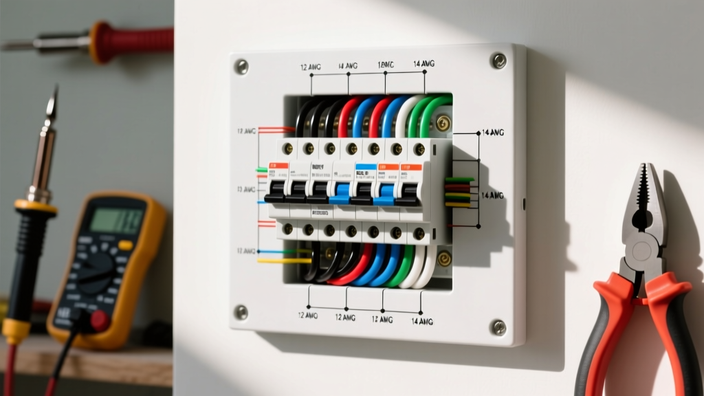
Before pulling wire, you must understand the physical topology represented in your wiring diagram for breaker box layouts. A standard single-phase, 3-wire residential panel (120/240V) consists of three primary bus bars:
- Hot Bus Bars (Lines A and B): Two uninsulated aluminum or copper bars that alternate 120V legs from the main breaker. Each leg provides 120V to neutral, and 240V across both legs.
- Neutral Bus Bar: A silver or tin-plated bar where all grounded (white or gray) conductors terminate. In a main service panel, this bar is bonded to the ground bar and the enclosure.
- Ground Bus Bar: A green-painted or bare metal bar where all equipment grounding conductors (bare copper or green) terminate.
Expert Insight: In a subpanel, the neutral and ground bus bars must remain isolated. The wiring diagram for breaker box subpanels will explicitly show a floating neutral bar, preventing objectionable current from traveling back along the grounding path, a violation of NEC Article 250.142.
NEC Wire Color Code Standards (AC Power)
Misidentifying a wire's purpose can lead to catastrophic short circuits or fatal shocks. The National Fire Protection Association (NFPA) 70: National Electrical Code mandates specific color coding for AC power systems. While older homes may feature legacy colors (like white wires used as hot switch legs without re-identification), all 2026 new installations and panel retrofits must strictly adhere to the following matrix.
Standard AC Color Code Matrix
| Voltage / Phase System | Hot (Line) Conductors | Neutral (Grounded) | Ground (Equipment) |
|---|---|---|---|
| 120/240V Single-Phase | Black (Line 1), Red (Line 2) | White or Gray | Bare Copper or Green |
| 208Y/120V 3-Phase (Wye) | Black, Red, Blue | White or Gray | Bare Copper or Green |
| 277/480V 3-Phase (Wye) | Brown, Orange, Yellow | Gray (White prohibited) | Bare Copper or Green |
| Any Voltage (Switch Leg) | Any color EXCEPT White, Gray, Green | N/A | N/A |
Note: If a white wire is used as a hot conductor (e.g., in a 240V appliance circuit or a switch loop), NEC Article 200.7(C) requires it to be permanently re-identified with black or red electrical tape or heat shrink at both termination points.
Wire Gauge Sizing for Breaker Amperage
The most critical data point when executing your wiring diagram for breaker box configurations is matching the breaker's ampere rating to the correct wire gauge. Sizing a breaker larger than the wire's ampacity is a leading cause of electrical fires, as the breaker will fail to trip before the wire insulation melts.
The following matrix is based on NEC Table 310.16 for copper conductors (THHN/THWN-2) in a standard 90°C rating, but derated to the 60°C or 75°C terminal temperature limits standard for most residential breakers (like the Square D HOM series or Siemens QT series).
Copper Wire Gauge to Breaker Size Matrix
| AWG Size | Max Breaker Amps | Wire Type / Insulation | Common Application |
|---|---|---|---|
| 14 AWG | 15 Amps | THHN / NM-B (Romex) | General lighting, standard receptacles |
| 12 AWG | 20 Amps | THHN / NM-B | Kitchen/bath small appliance circuits, GFCI/AFCI |
| 10 AWG | 30 Amps | THHN / NM-B | Electric water heaters, window AC units, dryers (120V) |
| 8 AWG | 40 Amps | THHN / THWN-2 | Electric ranges, older EV chargers, subpanel feeds |
| 6 AWG | 55 / 60 Amps | THHN / THWN-2 | Modern Level 2 EV chargers (48A continuous), subpanels |
| 4 AWG | 70 Amps | THHN / XHHW-2 | Heavy subpanel feeds, large HVAC condensing units |
| 2 AWG | 100 Amps | THHN / XHHW-2 | 100-Amp subpanel feeds, main service entrance (short runs) |
| 1/0 AWG | 125 Amps | THHN / XHHW-2 | 125-Amp main service panels |
| 2/0 AWG | 150 Amps | THHN / XHHW-2 | 150-Amp main service panels |
| 4/0 AWG | 200 Amps | THHN / XHHW-2 | Standard 200-Amp residential main service entrance |
Aluminum Wire Caveat: If your diagram specifies aluminum feeders (e.g., SER cable for subpanels), you must upsize by two gauges. A 200-amp main service requires 4/0 AWG copper, but 2/0 AWG aluminum is insufficient; you must use 4/0 AWG aluminum for a 200-amp service due to aluminum's lower thermal conductivity and higher expansion rate.
Precision Termination: Torque and Strip Lengths
Reading the wiring diagram for breaker box layouts is only half the battle; physical execution dictates longevity. Since the NEC introduced strict torque verification requirements in Article 110.14(D), inspectors now routinely check for proper lug torque. Under-torqued wires loosen over time due to thermal cycling, creating high-resistance arcing faults. Over-torqued wires snap the conductor strands or strip the breaker's aluminum set screw.
Standard Termination Specifications
- Strip Length: Most modern 15A to 50A breakers (including Eaton BR, Square D QO, and Siemens QP) require exactly 3/4 inch (19mm) of insulation stripped. Use a calibrated wire stripper, not a utility knife, to avoid nicking the copper, which creates a weak point that will snap under torque.
- Torque Values: Always reference the breaker's label. However, standard industry baselines for copper wire are:
- 14 to 10 AWG: 35 in-lbs (inch-pounds)
- 8 to 2 AWG: 45 in-lbs
- 1/0 to 4/0 AWG: 150 to 250 in-lbs (requires a heavy-duty torque wrench, not a standard screwdriver)
- Tooling: Use a calibrated digital torque screwdriver (e.g., CDI Torque 401SM or Wiha 64500). Standard manual screwdrivers cannot provide verifiable compliance.
For a deeper dive into federal safety mandates regarding wiring methods and terminal integrity, refer to OSHA Standard 1910.304 - Wiring Design and Protection, which outlines the legal requirements for secure and safe electrical terminations in commercial and industrial environments.
Common Edge Cases and Failure Modes
Even with a perfect wiring diagram for breaker box installations, field conditions introduce variables that cause failures. Watch for these specific edge cases:
1. The 'Double-Tap' Violation
Connecting two wires to a single breaker lug is a NEC violation unless the breaker is explicitly rated for it. While some Square D QO breakers feature dual-lug designs for 14-10 AWG wires, most standard Siemens and Eaton breakers do not. Fix: Install a wire nut (e.g., Ideal WireNut 341 Blue) with a 6-inch copper pigtail, or add an additional breaker to the panel.
2. Neutral and Ground Bar Overcrowding
NEC Article 408.41 dictates that each neutral terminal hole must receive only one neutral wire. Ground bars, however, can typically accept up to three ground wires of the same gauge per hole, provided the manufacturer's label allows it. Mixing neutrals and grounds on the same bar in a subpanel is an immediate fail during inspection.
3. Aluminum Wire Oxidation
If your diagram calls for aluminum SER cable feeding a subpanel, the exposed aluminum strands will oxidize rapidly when exposed to air, increasing resistance. You must coat the stripped aluminum conductors with an antioxidant compound (such as Noalox or Penetrox E) before inserting them into the breaker lugs or neutral bar. Failure to do so leads to thermal runaway at the termination point within 3 to 5 years.
4. AFCI/GFCI Pigtail Routing
Modern 2026 panels are saturated with Arc Fault (AFCI) and Ground Fault (GFCI) breakers. These breakers feature a white neutral pigtail that must terminate directly on the neutral bus bar. A common failure mode is routing the pigtail through a conduit or leaving it coiled tightly against the breaker's internal toroid sensor, which can cause nuisance tripping due to induced electromagnetic interference. Keep the pigtail routed cleanly and away from the hot bus bars.
Summary
A wiring diagram for breaker box configurations is your roadmap, but your knowledge of wire gauge limits, strict NEC color codes, and precise torque specifications is the vehicle that ensures a safe, code-compliant installation. Always verify your specific breaker manufacturer's torque labels, utilize calibrated tools, and respect the physical separation of neutrals and grounds in subpanel environments. By adhering to these rigorous standards, you ensure the longevity and safety of the electrical infrastructure.