
Bridging Resistive Heating and Inductive Motor Loads
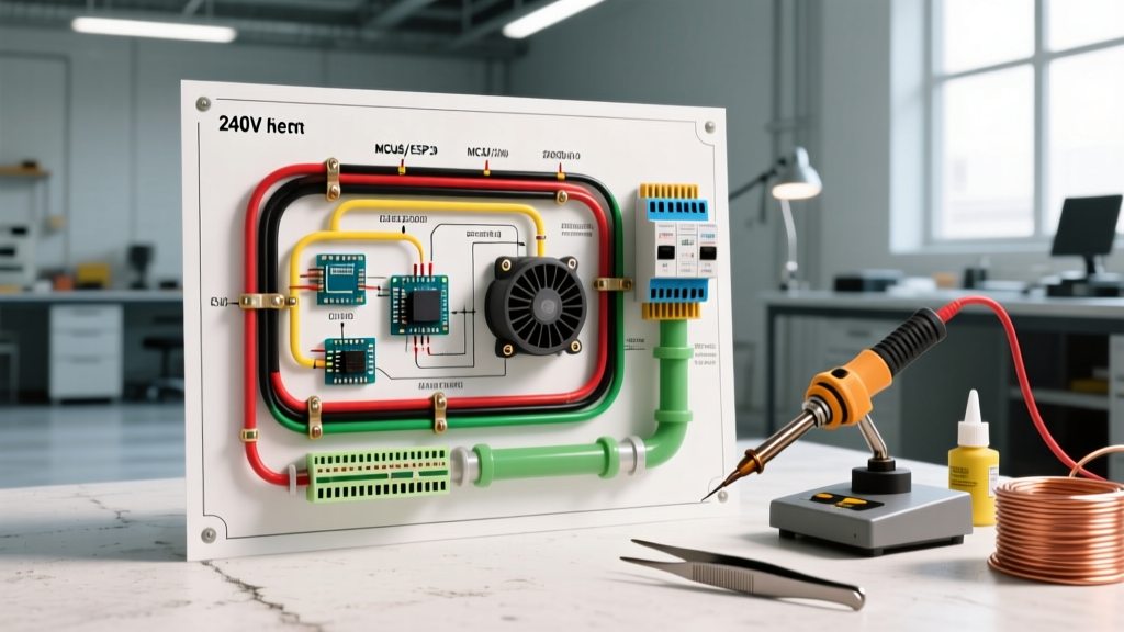
When most DIYers search for a 240v electric heater wiring diagram, they picture simple baseboard heaters with two wires and a ground. However, wiring a forced-air 240V electric heater—such as a garage unit heater, an electric furnace, or a duct heater—introduces a complex secondary circuit: the blower motor. From a motor wiring tutorial perspective, you are no longer just managing a purely resistive load; you are integrating inductive motor starting currents, run capacitors, and 24V control logic into a high-amperage 240V environment.
As of 2026, the U.S. Department of Energy's updated efficiency mandates have accelerated the transition from traditional Permanent Split Capacitor (PSC) motors to Electronically Commutated Motors (ECM) in electric heating units. This guide dissects the exact wiring topology, NEC sizing requirements, and motor integration strategies required to safely commission a 240V forced-air electric heater.
CRITICAL SAFETY WARNING: Working with 240V circuits carries a high risk of fatal arc flash and electrocution. Always verify the absence of voltage with a CAT III or CAT IV multimeter before touching any terminals. Ensure your local jurisdiction permits DIY electrical work; many regions require a licensed HVAC or electrical contractor for hardwired 240V appliance installations.
The 'No Neutral' Trap: 240V vs. 120/240V Circuits
The most common failure point in DIY electric heater installations stems from a fundamental misunderstanding of circuit topology. A standard 240V dedicated circuit consists of two hot legs (L1 and L2) and an equipment grounding conductor (EGC). It does not include a neutral wire.
If your electric heater's blower motor is rated for 120V, you cannot wire it to a pure 240V circuit. You have two code-compliant solutions:
- Solution A (Split-Phase): Run a 120/240V split-phase circuit (L1, L2, Neutral, Ground) using 3-conductor wire with ground (e.g., 10/3 NM-B or THHN in conduit). This allows 240V elements to connect across L1-L2, and the 120V motor to connect across L1-Neutral.
- Solution B (Step-Down Transformer): Run a pure 240V circuit (2-conductor with ground) and install an internal 240V-to-120V buck-boost transformer inside the heater chassis to power the 120V blower motor.
Most modern 240V unit heaters (like the Cadet RCP202S or Fahrenheat FUH series) utilize 240V blower motors specifically to eliminate the need for a neutral wire, simplifying the 240v electric heater wiring diagram to just two hots and a ground.
Core Component Anatomy in Forced-Air Heaters
To read the wiring diagram effectively, you must identify the primary control components that bridge the heating elements and the blower motor:
- Sequencers (e.g., White-Rodgers 586-902): Unlike contactors that snap closed instantly, sequencers use a bimetallic strip and a small heater coil to close contacts gradually. This stages the heating elements (e.g., Element 1 turns on, then Element 2) to prevent massive voltage drops and breaker trips.
- Blower Relay / Contactor: Often integrated into the first sequencer or operating as a standalone 24V coil relay, this component ensures the blower motor only runs when the heating elements are energized, preventing cold air drafts.
- Run Capacitor (PSC Motors): Typically rated between 5 MFD and 10 MFD at 370VAC. It provides the phase shift necessary to keep the single-phase blower motor running efficiently.
- Auto-Reset Limit Switch: Wired in series with the sequencer coils. If the blower motor fails and airflow stops, the limit switch detects the rising chassis temperature (usually tripping at 150°F - 180°F) and cuts power to the sequencer coils.
NEC Wire Gauge and Breaker Sizing Matrix
According to NFPA 70 (National Electrical Code) Article 424.4(B), fixed electric space-heating equipment is considered a continuous load. Therefore, the branch circuit conductors and overcurrent protection must be sized at 125% of the total maximum load (heating elements + blower motor + control transformer).
| Heater Capacity (kW) | Max Amp Draw @ 240V | 125% Continuous Load Calculation | Required Breaker Size | Min. Copper Wire Gauge (THHN/NM-B) |
|---|---|---|---|---|
| 5.0 kW | 20.8 A | 26.0 A | 30 Amp (2-Pole) | 10 AWG |
| 7.5 kW | 31.2 A | 39.0 A | 40 Amp (2-Pole) | 8 AWG |
| 10.0 kW | 41.6 A | 52.0 A | 60 Amp (2-Pole) | 6 AWG |
| 15.0 kW | 62.5 A | 78.1 A | 80 Amp (2-Pole) | 4 AWG |
Note: Always verify the specific nameplate MCA (Minimum Circuit Ampacity) and MOCP (Maximum Overcurrent Protection) on your unit, as manufacturer testing may dictate larger sizes based on internal motor starting surges.
Step-by-Step Motor and Element Wiring Procedure
Step 1: Line Voltage Termination
Route your 2-conductor with ground cable into the heater's junction box. Secure the cable with an appropriate Romex connector or conduit fitting. Terminate the bare copper ground to the chassis ground lug. Connect L1 and L2 to the main terminal block or directly to the line side of the primary sequencer and the blower contactor.
Step 2: Sequencer and Element Staging
In a multi-stage heater, L1 feeds the load side of Sequencer 1, which then jumper-feeds the load side of Sequencer 2. The heating elements connect between the line side of the sequencers and the L2 bus. This ensures that when the 24V control signal energizes the sequencer coils, the 240V current flows through the resistive elements.
Step 3: Blower Motor Integration (PSC)
If your unit uses a 240V PSC blower motor, you will find three or four wires emerging from the motor peckerhead:
- Common (C): Connects to L2 (or the blower relay's load side).
- Run (R): Connects to one side of the run capacitor and L1 (via the relay).
- Start (S): Connects to the opposite side of the run capacitor.
Ensure the run capacitor is securely strapped to the chassis. A loose capacitor will vibrate, eventually snapping the spade connectors and causing the motor to stall and overheat.
Step 4: 24V Control Circuit and Thermostat
The 240V-to-24V step-down transformer (usually 40VA) powers the control logic. Wire the transformer's primary side across L1 and L2. The secondary side (24V) routes to the wall thermostat (e.g., Honeywell TL7235A for line voltage, or a standard 24V smart thermostat if using an isolation relay). The thermostat acts as a simple switch, completing the 24V circuit to the sequencer coils.
2026 Update: ECM Motor Wiring in Electric Furnaces
As highlighted by U.S. Department of Energy guidelines on electric heating systems, modern high-efficiency electric furnaces now frequently utilize ECM blower motors. Unlike PSC motors, ECMs do not require a run capacitor. Instead, they feature an integrated electronic control module (ECM head).
Wiring an ECM in a 240V heater requires connecting the main 240V power to the motor module, plus a low-voltage harness that communicates with the furnace control board. The control board sends PWM (Pulse Width Modulation) or discrete 24V signals to the ECM head to dictate exact RPM profiles for heating, cooling, or continuous circulation. When troubleshooting an ECM that fails to spin, do not attempt to ohm-test the motor windings like a PSC; instead, verify the 240V supply to the module and check the control board for fault LED codes.
Troubleshooting Common Motor and Heating Failures
Even with a perfect 240v electric heater wiring diagram execution, components degrade. Here is how to diagnose the most frequent field failures:
Symptom: Blower Runs, But No Heat
Diagnosis: The sequencer coil is likely burnt out, or the 24V limit switch has tripped. Use a multimeter to check for 24V AC across the sequencer coil terminals. If 24V is present but the contacts don't close (no 240V on the load side), replace the sequencer. If 0V is present at the coil, trace the 24V circuit backward through the auto-reset and manual-reset limit switches.
Symptom: Heat Turns On, But Blower Motor Hums and Won't Spin
Diagnosis: This is a classic PSC motor failure. First, test the run capacitor with a multimeter's capacitance setting; a reading more than 10% below the MFD rating means the capacitor is dead. If the capacitor tests fine, the motor's internal centrifugal switch or start winding has failed, requiring a complete blower motor replacement.
Symptom: Heater Elements Glow Red and Overheat
Diagnosis: The sequencer contacts have welded shut due to electrical arcing over time. The elements are receiving constant 240V power regardless of the thermostat demand. Immediate Action: Turn off the 2-pole breaker at the main panel. Welded sequencers cannot be repaired and must be replaced immediately to prevent a chassis fire.
Final Commissioning Checklist
Before closing the chassis and applying permanent power, verify the following:
- All wire connections are torqued to manufacturer specifications (loose 240V connections will arc and melt terminal blocks).
- The equipment grounding conductor is continuous and unbroken.
- The blower wheel spins freely by hand without scraping the housing.
- The manual-reset limit switch is physically accessible from the exterior access panel, as required by UL 1042 standards.
By treating your 240V electric heater installation not just as a simple resistive load, but as a comprehensive motor and control circuit, you ensure decades of safe, efficient, and reliable operation.