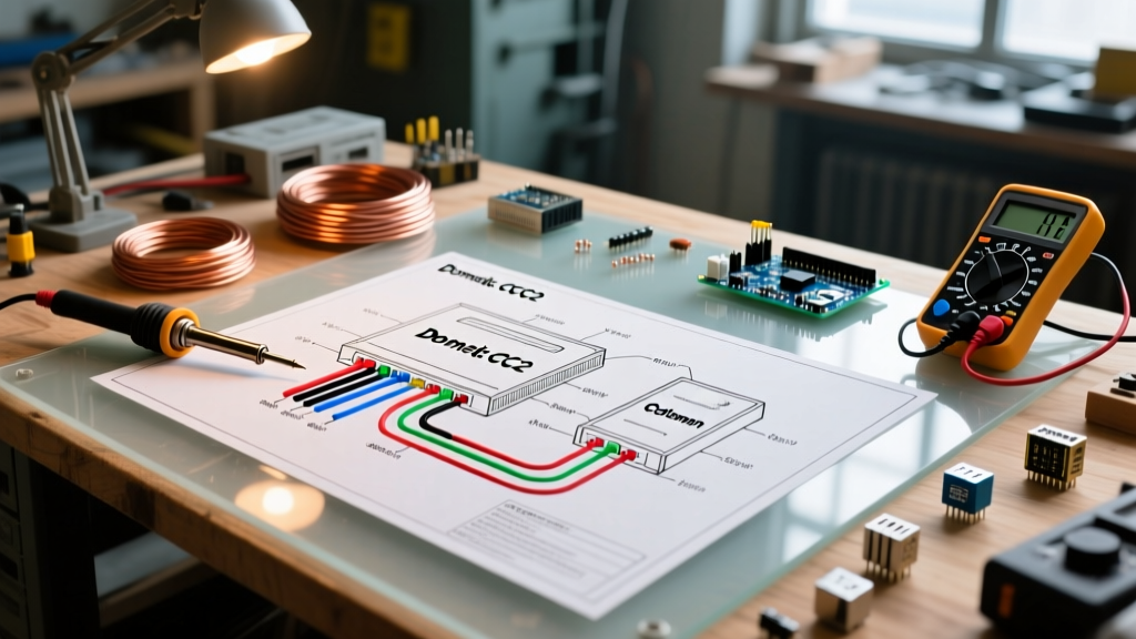

The Unique Architecture of RV Air Conditioning Systems
When tackling climate control upgrades in a motorhome, fifth wheel, or travel trailer, finding an accurate wiring diagram for AC unit thermostat configurations is fundamentally different from residential HVAC. Home thermostats typically rely on a 24V AC control circuit derived from a transformer. In contrast, recreational vehicles utilize a split-voltage architecture: 120V AC for the high-draw compressor and blower motors, and 12V DC for the thermostat logic and control board communication.
Misunderstanding this split is the leading cause of fried control boards and blown fuses in DIY RV repairs. As of 2026, the two dominant players in the North American RV market are Dometic (specifically the Comfort Control Center 2 or CCC2) and Airxcel / Coleman Mach. Both systems use low-voltage multi-conductor cables to send signals to the roof-mounted control board, which then switches the 120V relays. Below, we break down the exact pinouts, wire gauges, and failure modes for both systems.
Safety Warning: Before opening any RV AC junction box or thermostat wall plate, you must disconnect the vehicle from shore power, turn off the inverter, and disconnect the 12V battery bank. The 120V AC lines inside the AC shroud carry lethal current, even if the 12V thermostat appears dead.
Dometic CCC2 Thermostat Wiring Diagram & Pinout
The Dometic Comfort Control Center 2 (CCC2) is a multiplexed digital system. The wall-mounted thermostat does not directly switch the compressor; instead, it acts as a transceiver, sending digital data packets to the main control board located inside the roof AC shroud. The current replacement kit (Part #3314082.000, retailing around $165 in 2026) utilizes a standard RJ11 6-position, 4-conductor (6P4C) modular connector.
Dometic CCC2 RJ11 Pinout Matrix
| Pin Position | Wire Color | Function | Voltage / Signal |
|---|---|---|---|
| Pin 1 (Outer Left) | Red | 12V DC Power (+) | 12.0V - 14.2V DC |
| Pin 2 | Green | Data + (Multiplexed) | Digital Pulse (5V logic) |
| Pin 3 | Yellow | Data - (Multiplexed) | Digital Pulse (5V logic) |
| Pin 4 (Outer Right) | White | 12V DC Ground (-) | 0V Reference |
Expert Insight: The Dometic CCC2 system is highly sensitive to voltage drops. If the 12V supply at the thermostat drops below 11.5V under load (e.g., when the water pump or slide-out motors cycle), the digital communication bus will drop packets, resulting in an 'E-04' or 'E-05' communication error on the LCD screen. Always verify voltage at the wall plate with a multimeter while other 12V DC appliances are running.
Coleman Mach Analog 4-Wire Thermostat Wiring
While Airxcel (the parent company of Coleman Mach) has introduced digital smart thermostats, millions of RVs still utilize the classic Coleman Mach 3 and Mach 10 analog 4-wire wall controls. The standard replacement wall assembly (Part #8330-3862, approximately $95) uses a simple circuit-completion logic rather than multiplexed data.
Coleman Mach 4-Conductor Color Code
- Red Wire: +12V DC Constant Power (Fused at 5A or 10A on the main DC panel).
- White Wire: 12V DC Ground.
- Green Wire: Cool / Fan Control. When the thermostat calls for cooling, an internal relay bridges the Red wire to the Green wire, sending +12V to the roof board's 'Cool' terminal.
- Yellow Wire: Heat / Furnace Control. Bridges +12V to the roof board's 'Heat' terminal, which triggers the RV's propane furnace blower.
Unlike the Dometic system, the Coleman analog setup is essentially just switching 12V DC directly to the control board's optocouplers. This makes it incredibly robust and easy to troubleshoot with a basic $15 multimeter, but it requires dedicated wires for every function (which is why adding a heat pump to an older Coleman setup often requires pulling new 6-wire cabling through the walls).
Wire Gauge Selection and Routing Best Practices
The most common mistake DIYers make when replacing or extending RV thermostat wiring is using standard 24 AWG telephone wire from a big-box hardware store. While the physical RJ11 connectors will fit, 24 AWG wire suffers from severe voltage drop over the long distances typical in travel trailers (often 25 to 40 feet from the DC panel to the roof unit).
| Wire Gauge (AWG) | Max Recommended Run | Application | Voltage Drop @ 2 Amps |
|---|---|---|---|
| 24 AWG (Standard Phone) | 10 Feet | Patch cables only | ~1.0V (Unacceptable) |
| 22 AWG (Security Wire) | 20 Feet | Short RV runs (Vans) | ~0.6V (Marginal) |
| 18 AWG (4-Conductor) | 35 Feet | Standard Travel Trailers | ~0.25V (Ideal) |
| 16 AWG (4-Conductor) | 50+ Feet | Large 5th Wheels / Class A | ~0.15V (Optimal) |
Electromagnetic Interference (EMI) Routing Rules
According to guidelines published by the Recreation Vehicle Industry Association (RVIA), low-voltage communication cables must be routed separately from high-voltage AC lines. When running new 18/4 or 16/4 thermostat wire through your RV's walls or ceiling:
- Maintain a minimum separation of 4 inches from 120V AC Romex wiring.
- If the 12V DC thermostat wire must cross a 120V AC line, it must do so at a strict 90-degree angle to minimize inductive coupling and EMI.
- Never staple the low-voltage wire tightly against metal framing; use plastic wire loom or insulated cable clamps to prevent chafing and short circuits against the chassis ground.
Crimping RJ11 / RJ12 Connectors for RV Use
Because RVs experience constant vibration and torsional flexing while towing, standard residential crimping techniques often fail on the road. The copper strands work themselves loose from the RJ11 modular plug pins, leading to intermittent AC failures.
The Professional Method: Use a pass-through RJ11 crimper and pass-through connectors. Pass-through connectors allow the wire jacket to be pulled completely inside the plug, and the conductors to exit the front of the plug before being trimmed by the crimper's blade. This ensures the copper strands are seated at the absolute maximum depth, and the crimp tab bites directly into the outer PVC jacket for strain relief, not just the fragile copper wires. Always apply a small dab of dielectric grease to the exposed copper before crimping to prevent oxidation in high-humidity camping environments.
Troubleshooting Common Thermostat Wiring Failures
When your RV AC unit fails to respond to the thermostat, use this systematic diagnostic flow before ordering replacement parts:
1. The 'Dead Screen' Scenario (Dometic CCC2)
If the LCD screen is completely blank, the issue is almost always on the 12V DC supply side (Pins 1 and 4). Pull the RJ11 connector from the wall plate and use a multimeter to test the DC voltage between the Red and White wires. If you read 0V, check the 5A or 10A blade fuse in your RV's main DC distribution panel. If you read 12.6V but the screen is still dead, the internal voltage regulator on the CCC2 board has failed, requiring a full unit replacement.
2. The 'Short Cycling' Compressor (Coleman Mach)
If the AC compressor kicks on for 3 seconds, shuts off, and repeats, inspect the Green (Cool) wire. A frayed Green wire that is intermittently touching the 12V Red wire or the metal wall chassis will send rapid, erratic 12V pulses to the roof board's time-delay relay, causing it to fault out and lock the compressor to protect it from damage. Inspect the entire wire run, especially where it passes through the aluminum roof membrane gasket.
3. Furnace Blower Runs, But No Heat
If the thermostat calls for heat, the fan runs, but you get cold air, the wiring to the AC unit is likely fine. The Yellow wire successfully triggered the roof board, which sent a 12V signal to the propane furnace. The issue is likely a failed sail switch or igniter board on the furnace itself, not the AC thermostat wiring. For deeper diagnostics on RV propane furnaces, refer to the technical service bulletins available via the Airxcel RV Support Portal or Dometic's Official Support Hub.
Final Thoughts on RV Climate Upgrades
Upgrading or repairing your RV's air conditioning thermostat requires respecting the boundary between 12V DC logic and 120V AC power. By utilizing 18 AWG or 16 AWG 4-conductor wire, employing pass-through RJ11 crimping methods, and strictly adhering to the manufacturer pinouts, you can ensure reliable climate control whether you are boondocking in the desert or plugged into shore power at a humid coastal campground. Always verify your specific roof unit's model number, as manufacturers occasionally revise control board logic between production years.