
The Critical Nature of Marine Bilge Wiring
Mastering the correct wiring diagram for bilge pump with float switch configurations is a non-negotiable skill for marine DIYers and boat owners. Unlike standard 12V automotive circuits, a bilge pump is a life-safety device. A poorly executed wiring job doesn't just result in a blown fuse; it leads to a flooded hull, catastrophic engine damage, or a total vessel loss. According to marine insurance claims data, electrical failures and faulty bilge pump wiring are among the top causes of recreational boat sinkings at the dock.
In this comprehensive walkthrough, we will build a robust, fail-safe automatic bilge pump circuit featuring a manual helm override. We will use the industry-standard Rule 2000 GPH (Model 10A) pump paired with a Rule-A-Matic 1000 (RM-1) float switch, adhering strictly to the American Boat & Yacht Council (ABYC) E-11 standards for marine electrical systems.
The Golden Rule: Direct-to-Battery Power Sourcing
Before cutting a single wire, you must understand the most critical rule of bilge pump wiring: the circuit must be wired directly to the battery bank, completely bypassing the boat's main battery disconnect switch.
ABYC Safety Warning: If your bilge pump is wired to the main DC distribution panel, turning off the boat's main battery switch while docked will disable the automatic float switch. A sudden heavy rainstorm or a leaking through-hull fitting will sink the vessel because the pump has no power. The bilge pump must remain 'always hot'.
2026 Bill of Materials (BOM) & Specifications
To ensure longevity in a harsh, high-humidity saltwater environment, every component must be marine-rated. Automotive parts will corrode and fail within a single season. Below is the exact BOM with estimated 2026 retail pricing.
| Component | Recommended Model | Specification | Est. Cost (2026) |
|---|---|---|---|
| Bilge Pump | Rule 2000 GPH (Model 10A) | 12V, 8.4A Max Draw | $85.00 |
| Float Switch | Rule-A-Matic 1000 (RM-1) | Mercury-free, 10A Max | $48.00 |
| Helm Switch | Blue Sea 4283 WeatherDeck | ON-OFF-ON Toggle, 20A | $28.00 |
| Primary Wire | Ancor Marine Grade 14 AWG | Tinned Copper, Duplex | $1.25/ft |
| Connectors | Ancor Adhesive Heat Shrink | 16-14 AWG, Polyolefin | $18.00/pk |
| Fuse & Holder | Blue Sea ATC Inline Holder | 10A ATC Blade Fuse | $22.00 |
Step-by-Step Wiring Walkthrough
Step 1: Fusing the Positive Feed
Begin at the battery positive terminal. Run your 14 AWG tinned copper wire from the battery to the bilge area. Crucial ABYC Requirement: The inline ATC fuse holder must be installed within 7 inches of the battery positive terminal. This ensures that if the wire chafes against the hull anywhere along its run, the short circuit will blow the fuse before the wire can catch fire. For the Rule 2000 GPH (which draws 8.4A under load), install a 10A ATC blade fuse.
Step 2: Routing and Wire Management
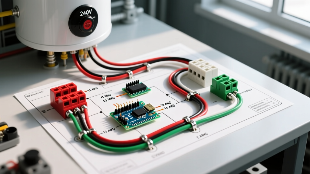
Route the duplex wire high up in the hull, securing it every 18 inches with UV-resistant cable ties. Keep the wire away from exhaust manifolds, sharp fiberglass edges, and steering cables. Use split-loom tubing anywhere the wire must pass through a bulkhead to prevent chafing. As noted by West Marine West Advisor, proper wire routing prevents the vast majority of mysterious voltage drops and short circuits in marine environments.
Step 3: Integrating the Float Switch
The Rule-A-Matic 1000 float switch features two wires: a solid brown wire (power in) and a brown wire with a white stripe (power out to the pump).
- Strip the ends of your fused positive feed from the battery and the solid brown wire from the float switch.
- Insert both into an adhesive-lined heat shrink butt connector.
- Crimp using a ratcheting crimp tool to ensure a gas-tight mechanical bond.
- Apply heat with a heat gun until the adhesive oozes out the ends, creating a waterproof seal that prevents capillary action from wicking bilge water up the copper strands.
- Connect the brown/white striped wire to the positive terminal on the bilge pump using the same adhesive heat shrink method.
Step 4: Wiring the Helm Manual Override
A proper wiring diagram for bilge pump with float switch setups always includes a manual override at the helm. This allows you to manually drain the bilge if the float switch becomes jammed by debris. We are using a Blue Sea 4283 (ON-OFF-ON) toggle switch.
- Center Terminal: Run a wire from the center terminal directly to the bilge pump's positive terminal (splicing in before the float switch connection).
- Top Terminal (Manual): Run a wire from the top terminal directly to the fused battery feed. Flipping the switch UP sends direct battery power to the pump, bypassing the float switch entirely.
- Bottom Terminal (Auto): Leave this terminal empty if you only want the center to be OFF and the top to be MANUAL. However, if you want an 'Auto' setting at the helm, wire the bottom terminal to the float switch's power-in feed. (Most modern setups rely on the float switch for Auto, using the helm switch strictly for Manual Override and Off).
Step 5: Grounding and Final Testing
Connect the negative wires from both the bilge pump and the float switch to a dedicated, sealed negative bus bar located high in the bilge. From the bus bar, run a single 14 AWG negative wire back to the battery negative terminal. Never ground a bilge pump directly to the engine block or a random hull bolt. Once connected, pour 5 gallons of water into the bilge. Verify the float rises and triggers the pump. Then, flip the helm toggle to MANUAL to ensure the override functions independently.
Troubleshooting Matrix: Common Failure Modes
Even with perfect wiring, environmental factors can cause issues. Consult this matrix for rapid diagnostics, referencing advanced troubleshooting techniques from BoatUS Expert Advice.
| Symptom | Probable Cause | Diagnostic Action & Fix |
|---|---|---|
| Pump runs continuously | Float switch stuck UP or debris jam | Inspect the strainer base. Clear slime, fishing line, or leaves trapping the float arm. |
| Pump hums but impeller won't spin | Severe voltage drop or seized motor | Use a multimeter to check voltage at the pump terminals under load. If below 11.5V, upsize wire to 12 AWG or check for corroded crimps. |
| Blown 10A fuse immediately upon manual activation | Dead short or locked rotor | Inspect wire chafing points at bulkheads. Disconnect pump and test motor directly with a jumper wire to isolate the short. |
| Pump works on Manual, but not on Auto | Float switch failure or broken brown wire | Bypass the float switch with a jumper wire. If the pump runs, the internal micro-switch in the Rule-A-Matic has failed and must be replaced. |
Final Thoughts on Marine Electrical Safety
Executing a flawless wiring diagram for bilge pump with float switch integration requires patience, the right adhesive-lined connectors, and strict adherence to ABYC fusing distances. By investing in tinned marine wire and a dedicated helm override, you ensure your vessel remains safe and dry, even when left unattended at the marina for months on end. Always re-test your bilge pump system at the start of the 2026 boating season and after any heavy haul-outs.