
Why Generic Advice Fails: The Power of Schematic Diagnostics
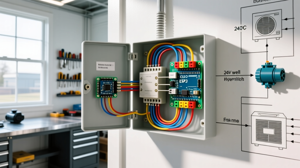
Most homeowners stare at a dead ceiling fixture and immediately blame the bulb or the switch. But when a new LED retrofit fails or a smart switch refuses to pair, the issue usually lies hidden in the walls. Relying on trial-and-error part swapping is not only expensive but potentially dangerous. Understanding a wiring diagram for house lights transforms a frustrating guessing game into a systematic, safe diagnostic process. As we navigate the 2026 National Electrical Code (NEC) cycle, with its stricter Arc-Fault Circuit Interrupter (AFCI) mandates and complex smart-home integrations, reading a schematic is no longer optional for serious DIYers and electricians.
This guide will teach you how to decode residential lighting schematics, trace voltage drops, and isolate failures in standard and 3-way switch loops using industry-standard methodologies.
Decoding the Schematic: Standard Symbols in Residential Lighting
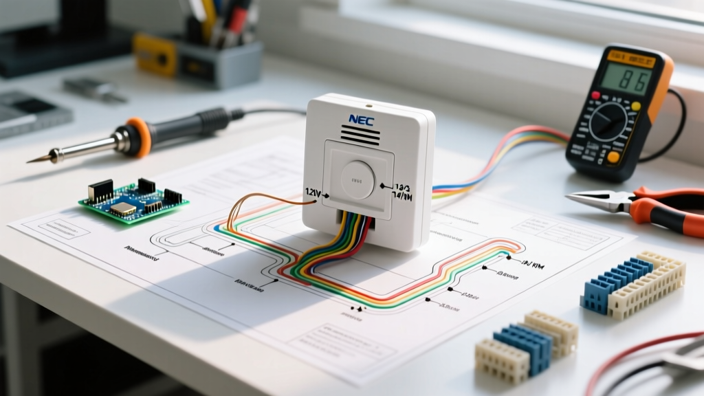
Before grabbing a multimeter, you must understand the visual language of electrical plans. A wiring diagram for house lights uses standardized symbols to represent physical components. Misinterpreting a 'switch loop' symbol for a 'continuous hot' is the most common cause of smart switch installation failures.
| Symbol / Notation | Component | Real-World Application & Troubleshooting Note |
|---|---|---|
| S with a loop (S-L) | Switch Loop | Power goes to the fixture first, then down to the switch. Crucial: No neutral wire is present at the switch box in older homes, preventing the use of standard smart switches like the Lutron Caseta PD-6ANS. |
| S3 | 3-Way Switch | Controls a light from two locations. Requires two 'traveler' wires. Troubleshooting requires testing continuity between travelers, not just voltage to ground. |
| Circle with 'H' | Hiccup / LED Driver | Indicates integrated LED fixtures with built-in drivers. Flickering here usually indicates a voltage drop issue or incompatible dimmer, not a bad bulb. |
| Line with 3 slashes | 14 AWG / 3-Wire Cable | Denotes 14/3 Romex (or NM-B). Used for 3-way switch travelers or split-receptacle wiring. Red wire is typically the switched hot or traveler. |
Diagnostic Flowchart: Tracing a Dead Light Circuit
When a circuit fails, do not immediately tear open the switch plate. Follow this sequential diagnostic flow to isolate the fault node.
- Panel Verification (The Source): Using a non-contact voltage tester (NCVT) like the Klein Tools NCVT-3 ($35), verify power is leaving the breaker. If the breaker has tripped, check for AFCI/GFCI nuisance tripping caused by failing LED drivers—a common issue in 2026 smart lighting setups.
- The Switch Box (The Control Node): Remove the switch plate. Test for 120V between the incoming hot (usually black) and the bare copper ground. If you have 120V here, the panel and branch wiring are intact. The fault is downstream.
- The Fixture Canopy (The Termination): If the switch tests good, move to the ceiling fixture. Test the switched hot against the neutral bundle. If you read 120V at the canopy but the light is dead, the fixture or its internal driver is the failure point.
- Neutral Continuity Check: If you have 120V at the switch, but 0V at the fixture when the switch is ON, you likely have a broken neutral connection in a wire nut daisy-chain inside the ceiling box.
Scenario A: The 'Bootleg Neutral' Smart Switch Failure
With the proliferation of Wi-Fi and Zigbee smart switches, many DIYers attempt to install devices requiring a neutral wire (like the Leviton Decora Smart DW6HD, ~$45) into older switch boxes that only have a hot, a switched hot, and a ground. A dangerous and code-violating workaround is tying the switch's neutral pigtail to the bare copper ground wire. This causes current to flow on the grounding path, which will immediately trip an AFCI breaker under the 2023/2026 NEC guidelines. Solution: Use a no-neutral switch like the Lutron Caseta PD-6WCL or pull a new 14/3 NM-B cable to bring a true neutral to the box.
Scenario B: 3-Way Switch Traveler Wire Failure
In a 3-way circuit, the two brass screws on the switch are connected to 'traveler' wires (often red and black in a 14/3 cable). If a light only works from one switch location, the schematic tells us the fault lies in the traveler connection or the mechanical contacts of the secondary switch. Use a Fluke 117 True RMS Multimeter (~$200) set to continuity mode (with the breaker OFF) to test the travelers end-to-end. A reading of 'OL' (Open Loop) indicates a broken wire inside the wall or a loose backstab connection.
Voltage Drop & Wire Gauge Matrix for Lighting Runs
According to the National Fire Protection Association (NFPA), while the NEC does not strictly mandate a specific voltage drop percentage for branch circuits, it recommends a maximum of 3% for lighting to ensure efficiency and prevent premature driver failure. When reviewing a wiring diagram for house lights on long runs (e.g., a detached garage or a long driveway lighting array), wire gauge selection is critical.
| Wire Gauge (Copper NM-B) | Max Amperage | Max Run Length (120V) for 3% Drop | Typical Application |
|---|---|---|---|
| 14 AWG | 15 Amps | ~50 feet | Standard interior bedroom/hallway lighting |
| 12 AWG | 20 Amps | ~65 feet | Kitchen under-cabinet, bathroom vanity, long exterior runs |
| 10 AWG | 30 Amps | ~80 feet | Heavy landscape lighting arrays, distant outbuildings |
Note: Run length is calculated as the total circuit length (one way), not the total wire length (out and back). Always calculate based on the total wattage of the connected LED load, though LED loads are typically a fraction of incandescent loads.
Advanced Troubleshooting: LED Flicker and Ghosting
A perfectly wired circuit according to the diagram can still suffer from 'ghosting'—where LED bulbs glow faintly when the switch is OFF. The U.S. Department of Energy (DOE) notes that this is often caused by capacitive coupling in long parallel cable runs, or by illuminated smart switches leaking a tiny amount of current (usually 1-2 milliamps) to power their internal Wi-Fi radios.
The Fix: Install a minimum load capacitor. The Lutron LUT-MLC (approx. $12) is wired in parallel across the light fixture's hot and neutral at the canopy. This provides a path for the leakage current, dropping the voltage below the LED driver's threshold and eliminating the ghost glow.
NEC Safety Reminder: As per OSHA electrical safety standards and NEC Article 110, always verify the absence of voltage using a properly rated CAT III or CAT IV multimeter before touching any bare conductors. Never rely solely on a non-contact voltage tester for final confirmation of a de-energized state.
Essential Diagnostic Tools for Lighting Circuits
- Fluke 117 True RMS Multimeter ($200): Essential for accurately reading voltage on circuits with non-linear LED loads. Standard average-sensing meters will give false readings on dimmer-controlled circuits.
- Klein Tools NCVT-3 Non-Contact Voltage Tester ($35): Dual-range (12V to 1000V) allows you to check for both line voltage and low-voltage landscape lighting faults.
- Gardner Bender GTR-1000 GFI/Receptacle Tester ($25): While primarily for outlets, it is invaluable for checking if a switch box has been illegally wired with reversed polarity or open grounds in retrofit situations.
Frequently Asked Questions (FAQ)
Can I use a 15A breaker with 12 AWG wire for house lights?
Yes. While 14 AWG is standard for 15A lighting circuits, using 12 AWG wire on a 15A breaker is perfectly legal and actually reduces voltage drop on long runs. However, you cannot use 14 AWG wire on a 20A breaker under any circumstances, as this violates NEC Article 240.4 and creates a severe fire hazard.
Why does my wiring diagram show a white wire connected to a black wire at the switch?
This indicates a 'switch loop' configuration. The white wire in the 14/2 cable is being used as the continuous hot feed down to the switch, while the black wire carries the switched hot back up to the fixture. Under current NEC codes, this white wire must be wrapped in black electrical tape or painted black at both ends to re-identify it as a hot conductor.
My AFCI breaker trips every time I turn on the LED dimmer. Is the wiring wrong?
Not necessarily. Older LED drivers and certain trailing-edge dimmers can create high-frequency electrical noise or inrush currents that mimic an arc fault to a sensitive AFCI breaker. Try replacing the dimmer with a modern, C-L or ELV-compatible model like the Lutron Diva LED+ (DVCL-153P). If the tripping persists, inspect the fixture canopy for pinched wires or loose neutral pigtails, which are actual arc-fault triggers.