
Mastering the Electrical Motor Wiring Diagram: An Installation Planning Guide
Grabbing a generic electrical motor wiring diagram off the internet and blindly connecting conductors is a fast track to burnt contactors, tripped mains, and catastrophic insulation failure. As industrial and commercial facilities upgrade to IE4 and IE5 premium efficiency motors in 2026, the complexity of motor control circuits has increased significantly. Proper installation planning requires a deep understanding of NEMA standards, NEC Article 430 requirements, and the specific starting characteristics of your load.
This guide provides a comprehensive framework for planning your motor installation, from decoding the nameplate to sizing conductors, selecting protection devices, and integrating Variable Frequency Drives (VFDs).
Decoding the Motor Nameplate: The Foundation of Your Diagram
Before you even look at a schematic, you must extract the critical data points from the motor nameplate. The nameplate dictates every subsequent decision in your wiring diagram. According to the U.S. Department of Energy's Motor Systems Guide, overlooking nameplate data is the leading cause of premature motor failure.
- FLA (Full Load Amps): The current the motor will draw at rated load and voltage. This is your baseline for wire sizing and thermal overload selection.
- LRA (Locked Rotor Amps): The current drawn when the rotor is stationary (starting current). This dictates your short-circuit breaker sizing and voltage drop calculations.
- Code Letter: Indicates the locked-rotor kVA per horsepower. Essential for calculating starting surges.
- Insulation Class & Amb Temp: Typically Class F (155°C) with a 40°C ambient rating. This affects the thermal overload trip curve you must select.
Selecting the Correct Electrical Motor Wiring Diagram
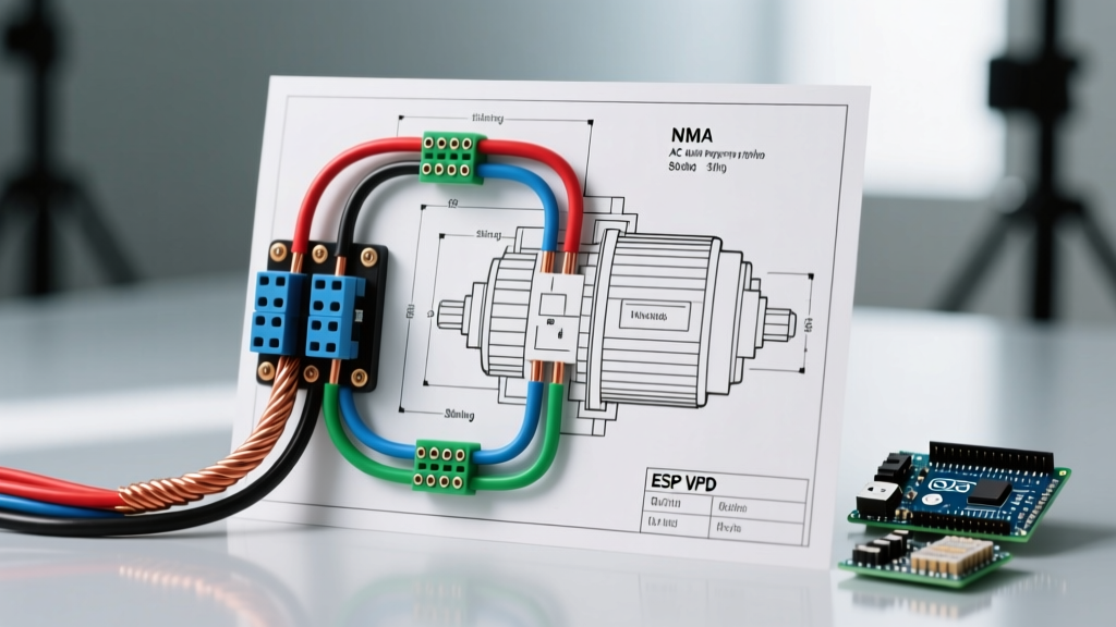
Motor wiring diagrams vary wildly based on phase, voltage, and starting method. Here is how to identify the correct configuration for your planning phase:
Single-Phase Motors (Split-Phase & Capacitor-Start)
For fractional to small integral horsepower applications (e.g., HVAC blowers, compressor pumps), you will typically use a Capacitor-Start, Induction-Run (CSIR) diagram. The critical planning element here is the centrifugal switch or potential relay that disconnects the start winding and start capacitor once the motor reaches 75% of synchronous speed. Reversing rotation requires swapping the start winding leads (typically T5 and T8) relative to the run winding.
Three-Phase Motors (9-Lead Dual Voltage)
Most industrial 3-phase motors are 9-lead, dual-voltage (e.g., 230/460V).
- Low Voltage (230V): The diagram will require a Delta or Wye configuration where coils are wired in parallel. You will tie leads (1,6,7), (2,4,8), and (3,5,9) together, applying power to the junctions.
- High Voltage (460V): The diagram requires a Series Wye or Series Delta configuration. Coils are wired in series, and leads 4, 5, and 6 are often tied together (in Wye) or left unconnected to the line (in Delta).
Conductor Sizing and NEC Compliance
Your electrical motor wiring diagram must account for conductor ampacity based on NEC Table 430.250. The NEC requires motor branch circuit conductors to be sized at a minimum of 125% of the motor's FLA. Furthermore, terminal temperature limitations (NEC 110.14(C)) usually restrict you to the 75°C column for THHN/THWN-2 wire, even though the wire itself is rated for 90°C.
| Motor HP | Voltage / Phase | FLA (Table 430.250) | Min Wire Ampacity (125%) | Min THHN Wire Size (75°C Col) | Max Inverse-Time Breaker (250%) |
|---|---|---|---|---|---|
| 3 HP | 230V / 1-Phase | 17A | 21.25A | 12 AWG (25A) | 40A |
| 5 HP | 230V / 3-Phase | 15.2A | 19A | 12 AWG (25A) | 40A |
| 10 HP | 460V / 3-Phase | 14A | 17.5A | 14 AWG (20A)* | 35A |
| 25 HP | 460V / 3-Phase | 34A | 42.5A | 8 AWG (50A) | 80A |
| 50 HP | 460V / 3-Phase | 65A | 81.25A | 3 AWG (100A) | 150A |
*Note: While NEC calculations may allow 14 AWG for 10HP @ 460V, local industrial specifications and voltage drop considerations often mandate a minimum of 12 AWG for mechanical durability.
Overload and Short-Circuit Protection Planning
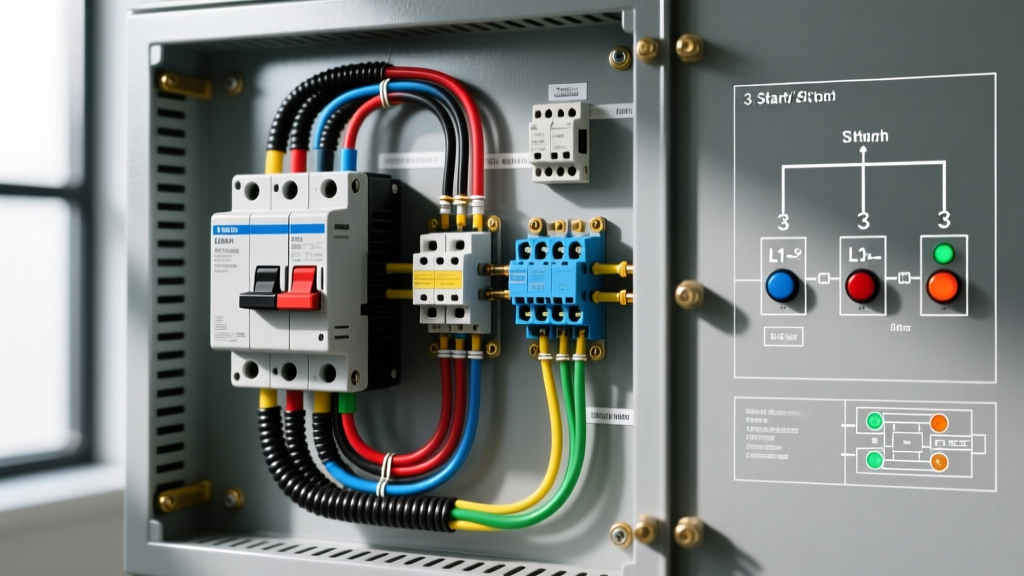
A common mistake when reading an electrical motor wiring diagram is confusing short-circuit protection with overload protection. They serve entirely different functions and are sized differently.
Critical NEC Distinction: The branch circuit breaker protects the wire from short circuits and ground faults (sized up to 250% of FLA per NEC 430.52). The thermal overload relay protects the motor from sustained overcurrent and single-phasing (sized between 115% and 125% of FLA per NEC 430.32).
Sizing Thermal Overloads (Real-World Example)
Suppose you are installing a 15 HP, 460V, 3-phase motor with a nameplate FLA of 19.5A and a Service Factor (SF) of 1.15. Because the SF is 1.15 or greater, NEC 430.32(A)(1) allows you to size the thermal overload at 125% of the nameplate FLA.
Calculation: 19.5A × 1.25 = 24.37A. You would select a NEMA Size 2 motor starter equipped with thermal overload heaters or an electronic dial setting precisely calibrated to 24.4A. In 2026, electronic solid-state overloads (like the Eaton PKZM4 or Siemens Sirius 3RB3) are heavily preferred over bimetallic heaters due to their immunity to ambient temperature fluctuations and built-in phase-loss detection.
VFD Integration: Modifying the Standard Wiring Diagram
When your installation plan includes a Variable Frequency Drives (VFD), the standard across-the-line electrical motor wiring diagram must be heavily modified. VFDs introduce high-frequency PWM (Pulse Width Modulation) waveforms that cause reflected waves and common-mode currents.
Essential VFD Wiring Additions
- Symmetrical Shielded VFD Cable: Standard THHN in conduit can act as an antenna for electromagnetic interference (EMI). Use dedicated VFD cable (e.g., Belden 29500 series or Lapp ÖLFLEX VFD) featuring three symmetrical ground wires and an overall copper shield. Expect to pay $3.00 to $6.00 per foot depending on gauge.
- Shaft Grounding Rings: Common-mode voltages can discharge through motor bearings, causing fluting and premature failure. Install an Aegis SGR (Shaft Grounding Ring) on the drive end of the motor. These cost roughly $35 to $60 and are non-negotiable for VFD-driven motors over 5 HP.
- dV/dt Filters: If the cable run between the VFD and the motor exceeds 100 feet, you must install a dV/dt filter or a sine wave filter at the VFD output to protect the motor's winding insulation from voltage spikes that can exceed 1,200V on a 460V system.
Common Installation Failure Modes & Edge Cases
Even with a perfect wiring diagram, physical installation realities can cause failures. According to Fluke's motor troubleshooting guidelines, electrical anomalies are responsible for the vast majority of motor burnouts.
- Voltage Unbalance: NEMA MG-1 standards dictate that a mere 1% voltage unbalance across the three phases will cause a 6% to 10% temperature rise in the motor windings. Always measure phase-to-phase voltage at the motor terminals under load, not just at the MCC (Motor Control Center).
- Single-Phasing: If one phase is lost while the motor is running, the remaining two phases will draw up to 173% of normal current to maintain torque. Without a phase-loss sensitive electronic overload, the motor will cook itself in minutes.
- Undersized Control Circuit Transformers: When wiring the control circuit (start/stop stations, PLC inputs), ensure the control transformer has enough VA (Volt-Amps) to handle the inrush current of the contactor coil. A NEMA Size 3 contactor coil can draw 150+ VA on startup. If your transformer is only 100 VA, the voltage will sag, causing the contactor to chatter and weld its contacts shut.
Pre-Energization Testing Protocol
Never throw the disconnect switch without completing this 4-step verification protocol:
- Megger Testing (Insulation Resistance): Disconnect the motor from the VFD or starter. Apply a 1000V DC megohmmeter to the windings-to-ground. For a 600V class motor, you must see a minimum of 10 Megohms. (Formula: [Nameplate Voltage + 1000] / 1000 = Min Megohms).
- Phase Rotation Check: Use a phase rotation meter (like the Fluke 870 series) to ensure the L1-L2-L3 sequence matches the motor's required rotation (CW or CCW). Swapping two leads on a reverse-rotation pump can destroy the impeller.
- Uncoupled Bump Test: Momentarily energize the motor uncoupled from the load to verify rotation and listen for bearing anomalies.
- Loaded Amperage Verification: Once coupled, measure the amperage on all three phases under full operational load. It must not exceed the nameplate FLA.
Final Thoughts on Motor Control Planning
A well-executed electrical motor wiring diagram is more than just connecting T1, T2, and T3. It requires a holistic approach to conductor sizing, thermal protection coordination, and harmonic mitigation. By adhering strictly to NFPA 70 (NEC) Article 430 and utilizing modern electronic protection relays, you ensure maximum uptime and safety for your facility's electromechanical systems.