
The Hidden Danger in Electric Fence Installations
When agricultural professionals and homesteaders search for a wiring diagram for electric fence systems, 90% of the available guides focus entirely on the low-impedance output side—stringing polywire, positioning step-in posts, and daisy-chaining insulators. However, the most critical and hazardous part of the installation is often ignored: the 120V AC power supply connection at the main breaker panel. Improperly wiring an energizer (charger) to your home or barn's electrical panel can lead to catastrophic backfeed during lightning strikes, nuisance tripping that leaves livestock uncontained, and severe fire hazards.
As of 2026, modern low-impedance energizers like the Gallagher M5800i or the Zareba 200 Mile AC draw relatively low continuous wattage (typically 15W to 40W), but they generate massive electromagnetic pulses and inrush currents. This guide provides the definitive AC panel and breaker wiring schematic for electric fence energizers, ensuring compliance with the latest National Electrical Code (NEC) standards while prioritizing operational reliability.
AC Panel to Energizer: The Core Wiring Schematic
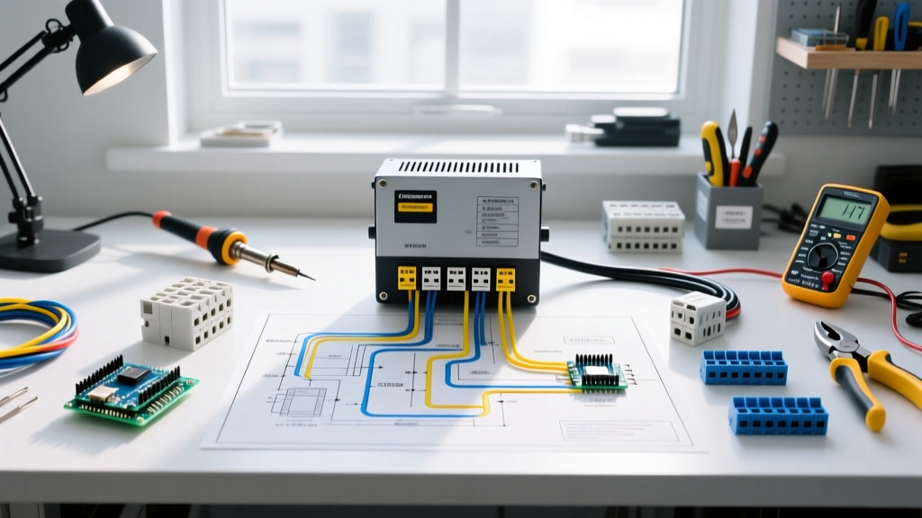
Unlike a standard outdoor receptacle used for power tools, an electric fence energizer requires a dedicated, hardwired branch circuit or a highly specific exterior receptacle setup to prevent voltage drop and interference. Below is the text-based schematic for routing power from your main service panel to the energizer's AC input terminals.
Step-by-Step Panel Routing
- Panel Termination: Install a dedicated 15A or 20A single-pole thermal-magnetic breaker (e.g., Square D Homeline or Eaton BR series) in the main service panel. Do not share this breaker with barn lighting or water heaters.
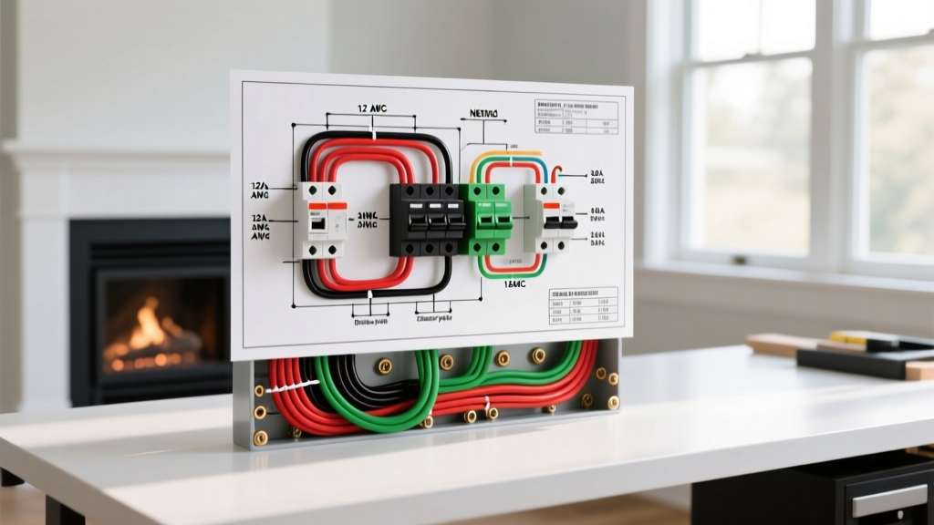
- Conduit and Wire Pull: Run 12 AWG or 14 AWG THHN copper conductors (Hot, Neutral, Ground) through a minimum 3/4-inch PVC Schedule 40 conduit from the panel to the exterior junction box or energizer mounting location.
- Exterior Disconnect/Junction: Terminate the conduit at a weatherproof NEMA 3R junction box or a heavy-duty in-use weatherproof receptacle cover (if using a plug-in energizer model).
- Energizer Connection: For hardwired models, connect the Hot (Black) to the energizer's L1 terminal, Neutral (White) to N, and Ground (Bare/Green) to the chassis ground lug. For plug-in models, ensure the receptacle is wired with standard polarity and tight terminal screws (torqued to manufacturer specs, typically 12-14 in-lbs).
Breaker Sizing and Wire Gauge Matrix
Selecting the correct wire gauge and breaker combination is vital to prevent voltage drop over long runs from the barn to the pasture. While the energizer itself draws less than 1 amp, the NEC requires specific minimums for branch circuits, and long agricultural runs demand voltage drop compensation.
| Breaker Size | Wire Gauge (Copper THHN) | Max Run Length (3% Voltage Drop) | Typical Use Case |
|---|---|---|---|
| 15 Amp | 14 AWG | 50 feet | Small homesteads, barn-adjacent paddocks |
| 15 Amp | 12 AWG | 80 feet | Standard residential fence installations |
| 20 Amp | 12 AWG | 115 feet | Large agricultural perimeters, multi-zone systems |
| 20 Amp | 10 AWG | 180 feet | Remote pasture energizers fed from main barn panel |
Note: Always calculate voltage drop based on 120V single-phase. If your run exceeds 180 feet, consider upgrading to a 240V circuit with a step-down transformer at the energizer site, or switch to a solar/battery-powered energizer to avoid trenching costs.
The Grounding Dilemma: Panel Ground vs. Fence Ground
This is the single most misunderstood aspect of electric fence wiring. The grounding system for the fence itself must never be physically bonded to the AC panel's grounding electrode system (the utility ground). According to guidelines reinforced by the National Fire Protection Association (NFPA) and agricultural safety standards, tying the fence ground to the AC panel ground creates a direct pathway for lightning strikes to enter your home's electrical wiring, potentially destroying appliances and starting fires.
The 10-Foot Separation Rule
The fence energizer requires its own independent ground rod system. The Penn State Extension and the University of Missouri Extension mandate that the energizer's ground rods must be driven into the earth at least 10 feet away from any utility ground rod, water pipe, or AC panel grounding electrode. In areas with high soil resistivity (dry, sandy, or rocky soil), a 50-foot separation is highly recommended.
Expert Field Tip: For a high-output energizer (over 50 joules), drive a minimum of three 8-foot copper-clad steel ground rods, spaced 10 feet apart, and connect them using continuous 12.5 AWG high-tensile galvanized wire or insulated 10 AWG copper wire. Use heavy-duty split-bolt connectors or bronze ground clamps, torqued tightly to prevent corrosion-induced resistance.
GFCI Nuisance Tripping vs. Code Compliance
A frequent point of failure in electric fence wiring diagrams is the integration of Ground Fault Circuit Interrupters (GFCI). NEC Article 210.8(G) generally requires GFCI protection for all 125V through 250V receptacles installed outdoors. However, the high-voltage, rapid-rise pulses generated by a fence energizer can induce capacitive coupling and electromagnetic interference (EMI) that cause standard GFCI receptacles to nuisance-trip, shutting down the fence and leaving livestock uncontained.
The Hardwired Workaround
To maintain code compliance while ensuring operational reliability, professional installers increasingly bypass outdoor receptacles entirely for permanent energizer setups. By hardwiring the energizer directly into a weatherproof junction box fed by a standard thermal-magnetic breaker in the panel, you eliminate the GFCI receptacle requirement (as hardwired equipment on dedicated circuits often falls under different NEC exceptions depending on local AHJ interpretations). If your local Authority Having Jurisdiction (AHJ) strictly mandates GFCI protection for the circuit, install a high-quality GFCI circuit breaker at the main panel rather than a standard outdoor GFCI receptacle, as panel-mounted GFCI breakers are generally more shielded from EMI and environmental degradation.
Surge Protection at the Panel
Because the energizer is highly susceptible to utility-side power surges, install a Type 2 Surge Protective Device (SPD) at the main panel, or use an inline surge suppressor rated for agricultural inductive loads on the dedicated branch circuit. A standard $35 whole-home SPD (like the Eaton CHSPT2ULTRA) can save a $600 Gallagher energizer from being fried by a grid-side transient voltage spike.
Real-World Troubleshooting: Panel-Side Failures
When an electric fence fails, DIYers immediately check the polywire and vegetation shorts. However, if the energizer's indicator lights are dead or flickering, the issue is often at the AC panel connection. Use this diagnostic checklist:
- Breaker Tripping Instantly: This rarely indicates a fence short. It usually means a direct short in the 120V AC wiring (e.g., a crushed conduit trapping the hot and ground wires) or moisture ingress in the exterior junction box. Disconnect the energizer and test the circuit with a multimeter.
- Energizer 'Clicks' but Reads Low Voltage: Check for severe voltage drop at the AC input terminals. If the panel reads 122V but the energizer terminals read 95V, your wire gauge is too thin for the run length, or a terminal screw at the breaker or receptacle is loose and arcing, creating high resistance.
- Shocks When Touching the Energizer Case: This is a critical emergency indicating a missing or broken equipment grounding conductor (EGC) between the panel and the energizer chassis. Immediately shut off the breaker. The chassis ground relies on the copper wire run back to the panel, not the fence ground rods.
- Flickering Barn Lights When Fence Pulses: The energizer is likely sharing a circuit with the barn lighting, or the neutral bus bar in the main panel has a loose connection. Move the energizer to a strictly dedicated breaker.
Final Safety and Inspection Protocols
Before energizing the system, verify all panel connections. In 2026, modern breakers require precise torque. Use a calibrated inch-pound torque screwdriver to tighten the breaker terminal and ground/neutral bus bar screws to the manufacturer's specifications (usually printed on the panel label, typically 20-30 in-lbs for 12 AWG wire). Finally, use a digital fence voltmeter to verify the output on the fence line, and an AC multimeter to confirm a stable 115V-120V at the energizer's input under load. Properly executing the AC panel wiring diagram ensures your electric fence remains a reliable, safe, and compliant perimeter defense for years to come.