
The Case for Upgrading the Ford 8N to 12 Volts
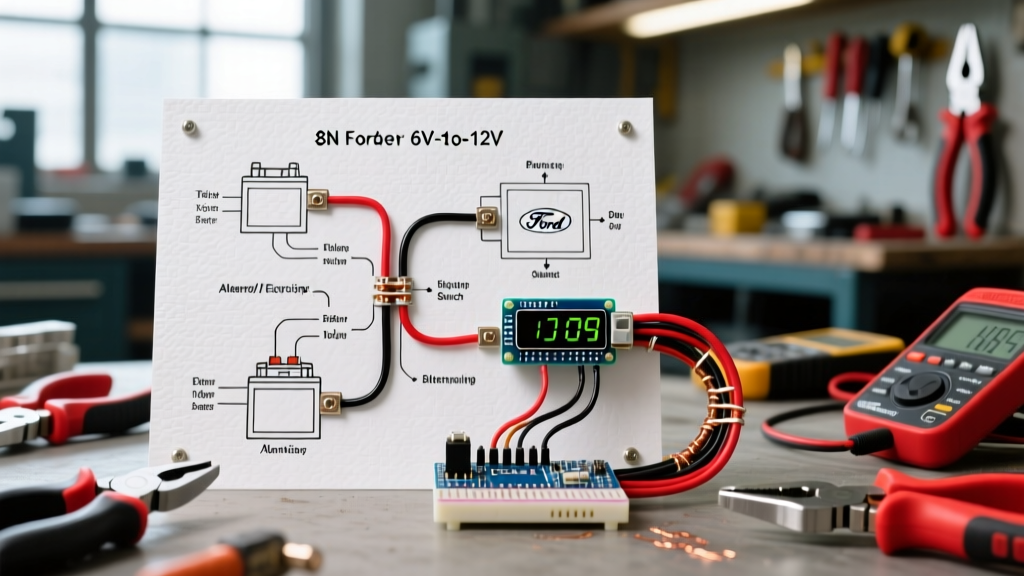
The Ford 8N tractor, produced between 1947 and 1952, originally left the factory with a 6-volt, positive-ground electrical system. While historically accurate, this 6V architecture is notoriously unreliable for modern agricultural and hobby farm use. Dim lights, sluggish cold-weather cranking, and constant generator maintenance plague original setups. Upgrading to a 12-volt, negative-ground system is the single most impactful modification you can make to an 8N. This comprehensive 12 volt wiring diagram for 8N Ford tractor conversions provides a step-by-step walkthrough to ensure your vintage machine starts reliably and charges efficiently in 2026 and beyond.
Critical Polarity Warning: The original 8N system is Positive Ground. A modern 12V system is Negative Ground. Failing to swap the battery cables and reverse the ammeter wiring before applying 12V power will instantly fry your ammeter and cause severe charging system damage.
Essential Parts List & 2026 Pricing Estimates
Before cutting a single wire, source high-quality replacement components. Avoid cheap, unbranded offshore alternators; stick to reputable remanufactured units or premium aftermarket brands.
- 1-Wire Alternator: Delco 10SI or 12SI (63 to 94 amps). Price: $95 - $140.
- 12V Ignition Coil: Standard Motor Products UC12 or NAPA IC14SB (requires external ballast). Price: $35 - $50.
- Ballast Resistor: 1.2 to 1.8 ohm ceramic resistor (e.g., NAPA ICR-11). Price: $12 - $18.
- 12V Battery: Group 24 or 25, minimum 700 CCA. Price: $140 - $180.
- Heavy-Duty Wiring Harness: Universal tractor loom or bulk SAE GXL wire. Price: $45 - $75.
- Alternator Mounting Bracket: Specific to Ford 8N front-mount generator replacement. Price: $35 - $55.
Step-by-Step Wiring Walkthrough
Step 1: Establishing Negative Ground & The Ammeter Swap
The foundation of your 12 volt wiring diagram for 8N Ford tractor conversion starts at the battery box. Remove the original 6V battery and install your new 12V Group 24/25 battery.
- Swap Battery Cables: Connect the heavy black ground cable to the Negative (-) terminal and route it to the tractor chassis (ensure bare metal contact). Connect the positive cable to the Positive (+) terminal.
- Reverse the Ammeter: Locate the ammeter on the dash. On the back, there are two wires. Simply swap their positions on the terminals. If you skip this, the gauge will read discharge when the tractor is charging, and vice versa.
- Reverse the Ignition Coil Primary Wires: Because you changed from positive to negative ground, the primary wires on your ignition coil must be swapped so that the negative terminal goes to the distributor points.
Step 2: Wiring the 1-Wire Alternator (Delco 10SI)
The 1-wire Delco alternator eliminates the need for the bulky, failure-prone original voltage regulator. According to The 8N Ford Tractor Information Site, this is the gold standard for 8N conversions.
- Mount the 10SI alternator using the dedicated 8N lower and upper brackets. Ensure the drive pulley aligns perfectly with the crankshaft pulley using a straight edge.
- Run a 10 AWG red wire from the large 'BAT' terminal on the back of the alternator directly to the battery-side terminal of your ammeter. Alternatively, you can route this to the battery post on the starter solenoid.
- Because it is a 1-wire unit, the alternator self-excites at roughly 1,200 RPM. Pro-Tip: After starting the tractor, give the throttle a quick blip to wake up the alternator and initiate charging.
- Remove the old generator, voltage regulator, and all associated wiring. Tape off and secure the old harness to prevent short circuits.
Step 3: Ignition Coil and Ballast Resistor Integration
The front-mount distributor on the 8N requires careful voltage management. Supplying a full 14.4V (alternator output) directly to a standard 12V coil will melt the points and burn out the coil internally.
- Run a 14 AWG wire from the ignition switch 'IGN' terminal to one side of the ceramic ballast resistor.
- Run a second 14 AWG wire from the other side of the ballast resistor to the Positive (+) terminal on the top of the front-mount coil.
- Run a wire from the Negative (-) terminal on the coil to the terminal on the side of the distributor housing.
- The ballast resistor drops the running voltage down to a safe 7V-9V, extending point life exponentially while still providing a hot, blue 12V spark during initial cranking (if wired with a bypass from the 'R' terminal on the starter solenoid, though the ballast-only method is standard for simplicity).
Step 4: Starter, Lights, and Accessory Circuits
While a 12V starter motor is ideal, many restorers successfully run the original 6V Bendix-style starter on 12V power. It will spin significantly faster, improving cold starts, but it will reduce the starter's overall lifespan due to increased brush wear. If you choose to keep the 6V starter, ensure you do not crank the engine for more than 5-10 seconds at a time to prevent overheating the armature.
For lighting, replace all 6V sealed beam headlights and taillights with 12V equivalents (e.g., H6024 sealed beams). Wire the headlight switch using 12 AWG wire routed through a 15-amp inline fuse directly from the ammeter's battery feed.
Wire Gauge & Routing Matrix
Proper wire sizing is critical to prevent voltage drop and fire hazards. The following matrix aligns with Southwire's SAE ampacity and sizing standards for low-voltage DC automotive applications.
| Circuit Name | Recommended Wire Gauge (AWG) | Wire Color Code | Fuse Rating | Routing Notes |
|---|---|---|---|---|
| Battery to Solenoid | 2/0 AWG (00) | Red / Black | None (Fusible Link) | Keep as short as possible; use heavy copper lugs. |
| Alternator to Ammeter | 10 AWG | Red | None | Route away from exhaust manifold and steering shaft. |
| Ammeter to Ignition Switch | 12 AWG | Red | 15A Inline | Pass through firewall grommet to prevent chafing. |
| Ignition to Ballast/Coil | 14 AWG | Purple or Yellow | None | Keep clear of moving fan blades. |
| Headlight Switch to Lamps | 12 AWG | Blue | 15A Inline | Use dielectric grease on all sealed beam connectors. |
| Horn Circuit | 14 AWG | Green | 10A Inline | Ensure 12V horn is installed; 6V horn will blow instantly. |
Common Failure Modes & Troubleshooting
Even with a perfect 12 volt wiring diagram for 8N Ford tractor conversions, field conditions and vibration can introduce faults. Here is how to diagnose the most common post-conversion issues:
1. Alternator Fails to Excite (No Charge)
Symptom: Ammeter reads zero or discharge at idle, but charges if you rev the engine high, or never charges at all.
Cause: The 1-wire Delco 10SI relies on internal electronic sensing that requires a specific RPM threshold to 'turn on'. Furthermore, a loose alternator belt will cause slippage, preventing the rotor from reaching excitation speed.
Fix: Check belt tension (should have 1/2 inch of deflection). If the belt is tight, blip the throttle upon startup. If it still fails, the internal diode trio may be damaged; replace the alternator.
2. Ignition Points Burning Rapidly
Symptom: Tractor runs rough after 10-20 hours; inspection reveals pitted, white-ash covered distributor points.
Cause: The ballast resistor was bypassed, wired incorrectly, or failed (open circuit), sending a full 14.4V through the points.
Fix: Use a multimeter to test voltage at the coil positive terminal while the engine is running. It should read between 7.5V and 9.0V. If it reads 13V+, immediately install or replace the 1.2 - 1.8 ohm ceramic ballast resistor. For deeper diagnostic procedures, reference the Yesterday's Tractors 8N 12-Volt Conversion Guide.
3. Starter Solenoid Chatter
Symptom: Turning the push-button starter switch results in a rapid clicking sound, but the engine does not crank.
Cause: Voltage drop between the battery and the solenoid, often caused by using undersized wire (e.g., 4 AWG instead of 2/0 AWG) or poor chassis grounding after the polarity swap.
Fix: Clean the ground connection on the chassis down to bare, shiny metal. Verify that the heavy battery cables are 2/0 AWG and that the copper lugs are properly crimped, not merely soldered.
Final Inspection and Safety Protocols
Before turning the key for the first time, double-check your ground polarity. Verify that the negative battery terminal is grounded to the chassis. Ensure all bare wire connections are covered with heat-shrink tubing—electrical tape will degrade and unravel due to the high under-hood temperatures and oil exposure common on the 8N. Once verified, start the tractor, let it idle, and blip the throttle to engage the alternator. Your ammeter should swing smoothly to the charge side, signaling a successful, reliable 12-volt conversion.