
The Critical Role of Bilge Pump Automation
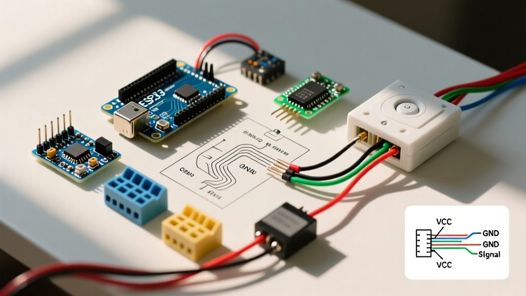
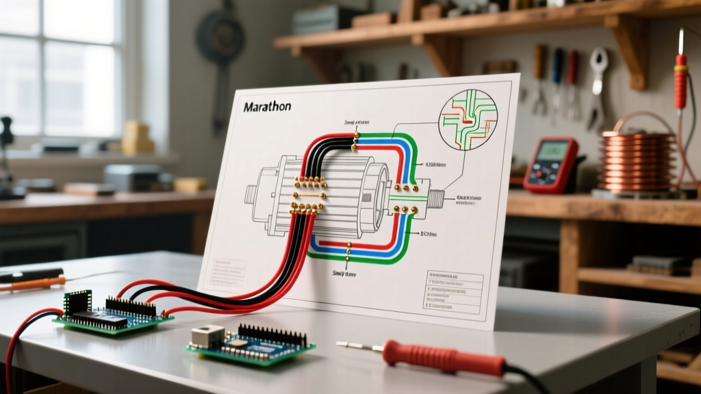
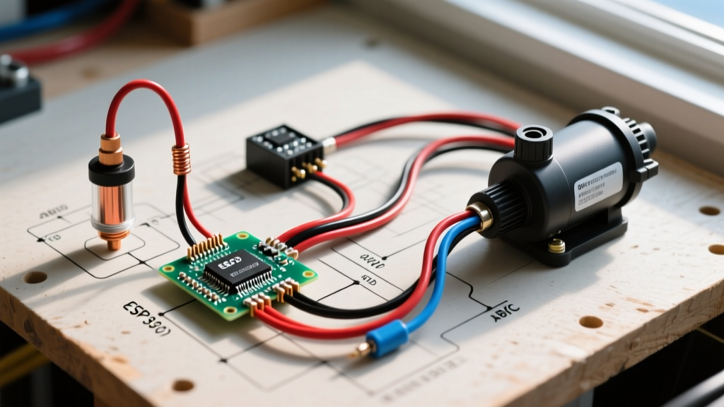
A reliable bilge pump is the single most important safety system on any marine vessel. When you are away from the boat, or asleep below deck, the bilge pump must operate autonomously to prevent sinking. Understanding the correct wiring diagram for float switch on a bilge pump is not just a matter of convenience; it is a critical safety requirement governed by strict marine electrical standards. In this 2026 motor wiring tutorial, we will break down the exact circuit architecture, ABYC (American Boat & Yacht Council) E-11 compliance requirements, and the specific components needed to build a fail-safe bilge pumping system.
Essential Components and 2026 Pricing
Before cutting any wire, you must gather marine-grade components. Automotive parts will fail rapidly in a high-humidity, saltwater environment due to stray current corrosion. Below is a recommended bill of materials based on current 2026 marine hardware pricing:
- Bilge Pump: Rule 500 GPH Submersible Pump (Model 25D) — Approx. $28.00
- Float Switch: Rule 25D-1 Automatic Float Switch (Non-mercury, dual-deck) — Approx. $34.00
- Manual Override Switch: Blue Sea Systems 9001e (3-Way: Off/Auto/Manual) — Approx. $45.00
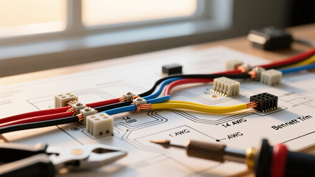
- Wire: Ancor 14 AWG Marine Primary Wire (Tinned copper, Type 3) — Approx. $1.30/ft
- Terminals: Ancor Heat Shrink Butt Splices and Ring Terminals — Approx. $15.00
- Overcurrent Protection: Blue Sea Systems ST Blade Fuse Block with 5A ATM Fuse — Approx. $22.00
Expert Note: Never use wire nuts or electrical tape in a bilge environment. The ABYC mandates the use of crimped connections with adhesive-lined heat shrink to prevent moisture ingress and capillary corrosion inside the wire strands.
ABYC Wire Sizing Chart for Bilge Motors
Voltage drop is the silent killer of bilge pumps. A 12V DC motor operating at 11V draws significantly more amperage to maintain wattage, leading to overheating and premature motor failure. According to ABYC E-11 Standards, bilge pump circuits must be sized for a maximum 3% voltage drop. Below is a reference chart for 14 AWG and 16 AWG tinned marine wire based on the Rule 500 GPH pump (which draws approximately 2.5 Amps at 12V).
| Wire Gauge (AWG) | Max 1-Way Run (Feet) | Max Amperage (3% Drop) | Recommended Fuse Size |
|---|---|---|---|
| 16 AWG | 8 ft | 3.0 Amps | 3A or 5A ATM |
| 14 AWG (Preferred) | 14 ft | 5.0 Amps | 5A ATM |
| 12 AWG | 22 ft | 7.5 Amps | 7.5A or 10A ATM |
Note: '1-Way Run' is the distance from the battery to the pump. The total circuit length is double this number. For comprehensive voltage drop calculations, consult the West Marine Wire Sizing Guide.
The Core Wiring Diagram for Float Switch on a Bilge Pump
A common and dangerous mistake made by amateur boaters is wiring the float switch directly to the battery via a simple on/off toggle. This violates ABYC standards because it lacks a manual override. If the float switch fails (e.g., jammed by debris), you must have a way to manually activate the pump. Therefore, the proper wiring diagram incorporates a 3-way switch (Off / Auto / Manual).
Connection Pathway: Step-by-Step
- Power Source to Fuse: Run 14 AWG red wire from the positive bus bar to a 5A fuse on the Blue Sea ST Blade fuse block.
- Fuse to 3-Way Switch: Run red wire from the output of the fuse to the center 'Common' terminal (Terminal 2) of the Blue Sea 9001e 3-way switch.
- Manual Override Leg: Run red wire from the 'Manual' terminal (Terminal 1) of the 3-way switch directly to the positive (brown) wire of the Rule bilge pump.
- Automatic (Float Switch) Leg: Run red wire from the 'Auto' terminal (Terminal 3) of the 3-way switch to the input wire (usually brown with a red stripe) of the Rule 25D-1 float switch.
- Float Switch to Pump: Run red wire from the output wire (solid brown) of the float switch to the positive (brown) wire of the bilge pump. (Splice the Manual leg and the Float Switch output leg together using a heat-shrink butt connector at the pump).
- Grounding: Run 14 AWG black wire from the negative (black) wire of the bilge pump directly to the vessel's negative DC bus bar. Do not ground through the engine block.
Execution: Best Practices for Marine Motor Wiring
Executing this wiring diagram for float switch on a bilge pump requires precision. Follow these motor wiring protocols to ensure longevity:
- Stripping: Use a precision wire stripper that will not nick the tinned copper strands. Nicked strands create hot spots under high amperage loads.
- Crimping: Use a ratcheting crimper (such as the IWISS IWS-1424A) calibrated for insulated heat-shrink terminals. A ratcheting tool ensures the exact compression ratio required for a gas-tight connection.
- Heat Shrinking: Apply heat from the center of the terminal outward. Watch for the adhesive to seep out of both ends, indicating a complete waterproof seal.
- Routing: Route bilge pump wiring as high as possible in the bilge. While the wire is marine-grade, prolonged submersion will eventually defeat the jacket. Use split-loom tubing and cable clamps every 18 inches.
Common Failure Modes and Troubleshooting
Even with a perfect installation, bilge systems require maintenance. Below is a troubleshooting matrix for common failure modes associated with float switch wiring:
| Symptom | Probable Cause | Diagnostic Action & Solution |
|---|---|---|
| Pump runs continuously, won't shut off | Debris jamming float switch or NO/NC wired backward | Clean the switch cage. Verify wiring is on the Normally Open (NO) contacts. |
| Pump runs on 'Manual' but not 'Auto' | Failed float switch or blown inline auto-leg fuse | Test float switch continuity with a multimeter while lifting the float manually. |
| Pump hums but impeller doesn't spin | Severe voltage drop or seized motor shaft | Measure voltage at the pump terminals under load. If below 11.5V, upgrade to 12 AWG wire. |
| Corrosion on battery terminals | Stray current from unsealed connections | Inspect all bilge crimps. Replace any terminal lacking adhesive-lined heat shrink. |
Expert FAQ
Can I wire two float switches to a single bilge pump?
Yes, and it is highly recommended for deep bilges. Wire a secondary 'high-water' float switch (like the Rule 25A) in parallel with the primary switch. Connect it to a separate alarm circuit and a dedicated secondary pump. Refer to advanced marine wiring diagrams on Marine How To for dual-pump architectures.
Does the float switch need its own fuse?
No. The ABYC requires overcurrent protection at the power source. Because the float switch is wired on the load side of the 3-way manual override switch, the single 5A fuse at the battery protects the entire circuit, including the float switch wiring.
How often should I test the float switch wiring?
You should manually lift the float switch to trigger the pump every 30 days. Pouring a bucket of fresh water into the bilge is the safest way to test the entire system, including the pump's ability to evacuate water and the check valve's ability to prevent backflow.