
Decoding the Briggs and Stratton Electrical Wiring Diagram for Riding Tractors
When servicing modern riding lawn tractors and utility vehicles powered by Briggs and Stratton engines—such as the Intek single-cylinders or the 810cc Vanguard V-Twins—understanding the electrical architecture is just as critical as mechanical timing. While the internal combustion side of these engines remains largely unchanged, the vehicle-side wiring harnesses have evolved significantly by 2026 to integrate complex Operator Presence Detection (OPD) interlocks, solid-state voltage regulators, and high-draw electric Power Take-Off (PTO) clutches.
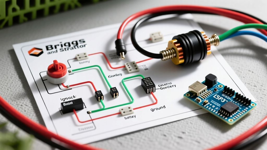
A standard Briggs and Stratton electrical wiring diagram for a riding tractor is not merely a map of wires; it is a logic circuit. Misinterpreting the difference between a magneto kill circuit and a 12V DC accessory feed is the leading cause of no-start conditions and burnt stators in the field. This guide breaks down the exact pinouts, voltage expectations, and failure modes of B&S powered tractor electrical systems.
The Flywheel Alternator and Stator Outputs
Unlike automotive alternators, Briggs and Stratton engines utilize a permanent-magnet flywheel alternator (stator) mounted under the engine blower housing. For heavy-duty riding tractors, the 15-amp and 20-amp stators (common part numbers include 593961 and 592477) are the industry standard.
Testing the Unregulated AC Output
Before the current reaches the battery, it is raw Alternating Current (AC). To verify stator health, you must bypass the voltage regulator and test the stator directly.
- Target RPM: 3600 RPM (Full throttle)
- Expected AC Voltage: 28 to 35 VAC across the two yellow stator wires.
- Resistance Check: With the engine off and wires disconnected, measure resistance across the yellow wires. A healthy 20A stator should read between 0.1 and 0.4 ohms. Anything reading 'OL' (Open Line) indicates a broken internal winding.
Voltage Regulator and Rectifier Integration
The 30+ VAC generated by the stator must be stepped down and rectified to charge a 12V lead-acid or AGM battery. Modern B&S riding mowers use a solid-state regulator/rectifier module, typically featuring a finned aluminum heat sink.
Expert Diagnostic Tip: If your tractor battery reads 12.6V at rest but drops to 11.8V while mowing at full throttle, your regulator is likely failing under thermal load. Use a thermal camera to scan the regulator fins; temperatures exceeding 180°F (82°C) combined with low DC output confirm internal diode degradation.
Wiring Pinout for the B&S Regulator:
- Yellow Wire 1 (AC In): Connects to Stator Yellow Wire A.
- Yellow Wire 2 (AC In): Connects to Stator Yellow Wire B.
- Red Wire (DC Out): Connects to the vehicle's main 12V B+ bus (often routed through a 20A inline fuse to the ignition switch 'B' terminal).
- Black Wire / Mounting Tabs (Ground): Must have a pristine, bare-metal connection to the engine block. Star washers are mandatory here to bite through paint and prevent voltage drops.
Ignition Switch Terminal Pinout Matrix
The ignition switch is the central routing hub for the tractor. Most B&S-powered tractors use a standard 5-pin or 6-pin switch. Understanding these terminals is vital for reading any Briggs and Stratton electrical wiring diagram.
| Terminal Letter | Function | OFF Position | RUN Position | START Position |
|---|---|---|---|---|
| B | Battery (12V+ Input) | Open | Connected to A, L | Connected to A, S, L |
| S | Starter Solenoid | Open | Open | Receives 12V from B |
| A | Accessory / 12V Feed | Open | Receives 12V from B | Receives 12V from B |
| M | Magneto (Ignition Kill) | Connected to G | Open | Open |
| G | Ground | Connected to M | Open | Open |
| L | Lights / Hourmeter | Open | Receives 12V from B | Receives 12V from B |
Note: In the OFF position, the 'M' and 'G' terminals bridge together. This grounds the ignition coil's primary winding, collapsing the magnetic field and killing the spark.
The Safety Interlock System: Wiring the Kill Circuit
By 2026, the Outdoor Power Equipment Institute (OPEI) safety standards mandate rigorous Operator Presence Detection (OPD) on all riding mowers. Briggs and Stratton engines interface with the tractor manufacturer's interlock module (often a small black box with 4 to 6 spade connectors) to manage engine killing logic.
Standard Interlock Logic Gates
- Starting Condition: Brake pedal depressed + PTO switch disengaged + Transmission in neutral/park = Interlock module allows 12V to the starter solenoid 'S' terminal.
- Running Condition (PTO Engaged): If the seat switch opens (operator stands up) while the PTO is engaged, the interlock module instantly grounds the 'M' wire, killing the engine within 2 seconds to prevent blade-related injuries.
- Running Condition (PTO Disengaged): If the operator leaves the seat with the PTO off and the parking brake set, the engine is permitted to stay running.
Common Failure Mode: Moisture ingress into the seat switch connector causes a false 'open' circuit. The interlock module thinks the operator has left the seat and grounds the magneto kill wire, resulting in an engine that dies randomly over bumps.
Electric PTO Clutch Wiring and Relay Integration
Modern electric PTO clutches (manufactured by Ogura or Warner) require significant amperage to engage the electromagnetic coil—typically between 2.5A and 4.0A at 12V DC. Running this current directly through the dashboard PTO toggle switch will melt the switch contacts within a single mowing season.
Proper PTO Wiring Architecture:
- Route a heavy-gauge (12 AWG) 12V+ feed directly from the battery to a 30A automotive relay.
- Use the dashboard PTO switch to trigger the relay's low-current coil (85/86 terminals) using 16 AWG wire.
- Feed the PTO clutch from the relay's high-current output (terminal 87).
- Critical: Install a reverse-biased flyback diode across the PTO clutch terminals. When the clutch disengages, the collapsing magnetic field generates a massive voltage spike (back-EMF) that can fry the tractor's solid-state voltage regulator if not suppressed.
Wire Gauge Selection and Routing Standards
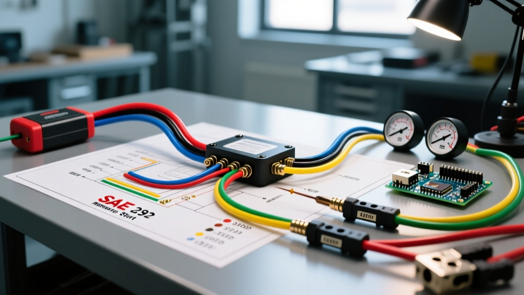
When repairing or rebuilding a B&S tractor harness, adhere to the SAE J1128 standard for low-tension primary cables. Using undersized wire leads to voltage drop, which starves the PTO clutch of current, causing it to slip and overheat.
- Starter Solenoid & Battery Main Feed: 10 AWG or 8 AWG (Stranded copper)
- PTO Clutch High-Current Feed: 12 AWG or 14 AWG
- Stator AC Output & Regulator DC: 14 AWG (Must be rated for high heat near the engine block)
- Ignition Switch, Interlocks, and Lighting: 16 AWG or 18 AWG
Step-by-Step Troubleshooting: No-Charge Condition
If your tractor requires a jump start every time you use it, follow this diagnostic sequence before replacing parts:
- Verify Battery Health: Load test the battery. A bad cell will pull the regulator voltage down, making it appear as though the stator is failing.
- Check the Inline Fuse: Locate the 20A fuse between the regulator's red wire and the ignition switch 'B' terminal. A blown fuse here severs the charging circuit.
- Measure Regulator DC Output: With the engine at 3600 RPM, probe the red wire at the regulator. You should read 14.1V to 14.4V DC. If it reads 0V, but the AC stator test (28-35 VAC) passed, the regulator is dead.
- Inspect the Ground Path: Use a multimeter to measure voltage drop between the regulator casing and the battery negative terminal. A reading above 0.1V indicates a corroded ground path. Clean the mounting bolts and apply dielectric grease.
Frequently Asked Questions
Can I run a Briggs and Stratton engine without a battery?
Technically, the engine will run if the stator and ignition coil are independent (common on older models). However, on modern tractors with a shared stator and solid-state regulator, running the engine without a connected battery acts as an open circuit. The unregulated AC voltage will spike, instantly destroying the regulator's internal diodes. Always keep a battery in the circuit to act as a voltage buffer.
Where can I find the exact schematic for my specific engine model?
Briggs and Stratton provides comprehensive wiring schematics tied directly to your engine's model, type, and code numbers. You can download the official PDF manuals and wiring diagrams directly from the Briggs and Stratton Official Manuals portal. Always use the engine code, not just the tractor manufacturer's model number, to ensure accuracy.
Why does my stator wire insulation keep melting?
Melting insulation on the yellow stator wires is a hallmark of a shorted internal winding or a failed regulator that is allowing DC current to back-feed into the AC stator windings. If you see melted yellow wires, replace both the stator and the regulator simultaneously, and verify that the cooling fins under the blower housing are completely free of grass clippings and debris.