
The Critical Role of NEC Compliance in 3-Phase Motor Wiring
Three-phase induction motors are the undisputed workhorses of modern industrial and commercial infrastructure, driving everything from heavy HVAC compressors to manufacturing conveyor systems. However, interpreting and executing a wiring diagram for three phase motor applications requires far more than simply connecting lines to terminals. Improper wiring, undersized conductors, or incorrect protection coordination can lead to catastrophic thermal events, arc flashes, and devastating equipment failure.
From a safety and code compliance perspective, every motor circuit must adhere strictly to the National Electrical Code (NEC / NFPA 70), specifically Article 430 (Motors, Motor Circuits, and Controllers). This guide breaks down the anatomy of a code-compliant three-phase motor wiring diagram, detailing exact sizing calculations, protection coordination, and modern safety protocols required for 2026 installations.
Deconstructing the Power and Control Circuits
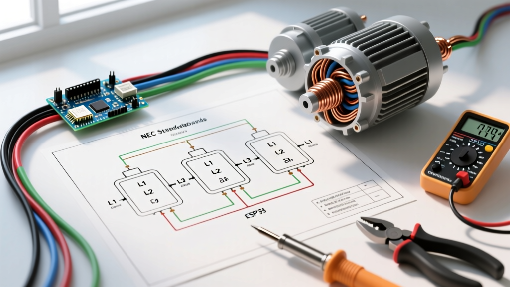
A standard Direct-On-Line (DOL) wiring diagram for three phase motor systems is divided into two distinct sections: the power circuit and the control circuit. Understanding the isolation between these two is fundamental to safe troubleshooting and design.
The Power Circuit Path
The power circuit carries the full load current (FLC) and fault current. The standard sequence from the distribution panel to the motor terminal box is:
- Disconnect Switch / Motor Circuit Protector (MCP): Provides a visible means of disconnect and short-circuit protection.
- Fuses or Circuit Breaker: Sized strictly for branch circuit short-circuit and ground-fault protection (not overload).
- Magnetic Contactor: The heavy-duty relay that physically switches the three phases (L1, L2, L3) to the motor.
- Overload Relay: Monitors current draw and drops out the contactor coil if the motor exceeds its thermal limits.
- Motor Terminals (T1, T2, T3): The final connection point inside the motor peckerhead.
The Control Circuit Isolation
Modern code-compliant diagrams rarely use line voltage (e.g., 480V) for control logic due to the severe arc flash and shock hazards it presents to technicians. Instead, a step-down control transformer (e.g., 480V primary to 120V secondary) is utilized. The secondary side must be grounded and protected by primary and secondary fuses as dictated by NEC Article 725. This ensures that pushbuttons, selector switches, and PLC inputs operate at a safer, extra-low voltage.
Code Alert (NEC 430.102): You must provide a disconnecting means for the motor controller that is capable of disconnecting the controller from the circuit. A single disconnect must simultaneously open all ungrounded conductors to both the motor and the control transformer.
Motor Full-Load Current (FLC) and Conductor Sizing Matrix
One of the most common and dangerous mistakes in motor wiring is sizing conductors based on the motor's nameplate Full-Load Amps (FLA). The NEC explicitly forbids this for conductor sizing. According to NEC Article 430.6(A), you must use the NEC Table 430.250 FLC values, which are standardized and typically higher than the nameplate rating, to account for variations in motor efficiency and power factor across different manufacturers.
Furthermore, NEC 430.22 requires that branch circuit conductors supplying a single continuous-duty motor be sized at 125% of the NEC table FLC. Below is a sizing matrix for standard 480V, 3-phase, 60Hz NEMA Design B motors using 75°C rated THHN/THWN-2 copper conductors in a standard EMT conduit.
| Motor HP | NEC Table FLC (Amps) | Min Conductor Ampacity (125%) | Recommended AWG (75°C THHN) | Max Inverse-Time Breaker (250%) |
|---|---|---|---|---|
| 5 HP | 7.6 A | 9.5 A | 14 AWG (20A rating) | 15 A |
| 10 HP | 14.0 A | 17.5 A | 12 AWG (25A rating) | 35 A |
| 25 HP | 34.0 A | 42.5 A | 8 AWG (50A rating) | 80 A |
| 50 HP | 65.0 A | 81.25 A | 3 AWG (100A rating) | 150 A |
| 100 HP | 124.0 A | 155.0 A | 1/0 AWG (170A rating) | 300 A |
Overload Protection vs. Short-Circuit Protection
A critical concept in any wiring diagram for three phase motor systems is the separation of overload protection from short-circuit/ground-fault protection. They serve entirely different physical functions and are governed by different NEC tables.
Branch Circuit Short-Circuit and Ground-Fault Protection
The circuit breaker or fuses at the panel are designed to protect the wiring from catastrophic short circuits and ground faults, not the motor itself. NEC Table 430.52 allows for massive over-sizing of these devices to accommodate the high inrush current (Locked Rotor Amps) a motor draws during startup. For a standard inverse-time circuit breaker, the maximum rating is 250% of the FLC. If a 10 HP motor draws 14A FLC, the breaker can legally be sized up to 35A (14 x 2.5 = 35), even though the wire is only sized for 17.5A. This is safe because the overload relay protects the wire from continuous over-current.
Selecting the Right Overload Relay
Overload relays protect the motor windings from slow, thermal degradation caused by mechanical overloading or single-phasing. Under NEC 430.32(A)(1), the overload device must be set to trip at 115% of the motor nameplate FLA (for motors with a 1.15 service factor).
In 2026, legacy bimetallic thermal overload relays are increasingly being replaced by solid-state electronic overloads like the Schneider Electric TeSys Giga or Eaton PKZM4 series. These advanced units provide precise phase-loss detection, phase imbalance tripping, and jam protection, drastically reducing motor burnout rates.
Grounding, Bonding, and Equipment Grounding Conductors (EGC)
A motor frame must be permanently and effectively grounded. Relying on the metal conduit (EMT/Rigid) alone as the sole equipment grounding conductor is permitted by the NEC in specific scenarios, but best practice—and often local code mandate—requires pulling a dedicated copper Equipment Grounding Conductor (EGC) inside the raceway.
The EGC must be sized according to NEC Table 250.122, which bases the ground wire size on the rating of the overcurrent protective device (the breaker), not the motor FLC. For example, if your 10 HP motor circuit utilizes a 35A breaker, Table 250.122 mandates a minimum 10 AWG copper EGC. Undersizing the EGC can result in the breaker failing to trip instantaneously during a ground fault, leaving the motor frame energized at lethal potentials.
Arc Flash Mitigation and LOTO Protocols (NFPA 70E)
Executing a wiring diagram is only half the battle; maintaining and troubleshooting the panel safely is where lives are saved. Under NFPA 70E standards, three-phase motor control centers (MCCs) and disconnects frequently fall into Category 2 or Category 3 Arc Flash PPE boundaries due to the high available fault current on industrial 480V systems.
- Category 2 (8 cal/cm²): Requires an arc-rated shirt and pants, a faceshield with an arc-rated balaclava, and heavy-duty voltage-rated gloves with leather protectors.
- LOTO Compliance: Before opening any motor terminal box or contactor, technicians must adhere to OSHA 1910.147 Lockout/Tagout procedures. This involves isolating the main disconnect, applying a physical padlock, and verifying zero energy state using a CAT IV multimeter on all three phases and the ground.
Troubleshooting Common Wiring Faults
Even with a perfect wiring diagram for three phase motor installations, field conditions can introduce faults. Understanding these edge cases is vital for safety and compliance.
Single-Phasing
Single-phasing occurs when one of the three power lines is lost (e.g., a blown fuse or a broken utility line). The motor will attempt to continue running on the remaining two phases, drawing up to 250% of its normal current on those legs. Without a phase-loss sensitive electronic overload relay, the motor will rapidly overheat and the windings will melt, potentially igniting a fire. Modern solid-state relays detect this imbalance within milliseconds and drop the contactor.
Phase Reversal
Swapping any two of the three phase legs (e.g., swapping L1 and L2) will reverse the direction of the motor's rotation. In applications like centrifugal pumps or escalators, this can cause immediate mechanical destruction or severe safety hazards. Code-compliant diagrams for critical infrastructure often include a Phase Sequence Relay wired into the control circuit, which prevents the main contactor from engaging if the phase rotation is incorrect.
Final Code and Safety Takeaways
Designing and wiring a three-phase motor circuit is an exercise in strict mathematical compliance and hazard mitigation. By adhering to NFPA 70 (NEC) Article 430 for sizing, utilizing Table 250.122 for grounding, and enforcing rigorous troubleshooting and testing protocols, electrical professionals ensure that these powerful machines operate safely and reliably for decades.