
Intro: Setting the Visual Stage
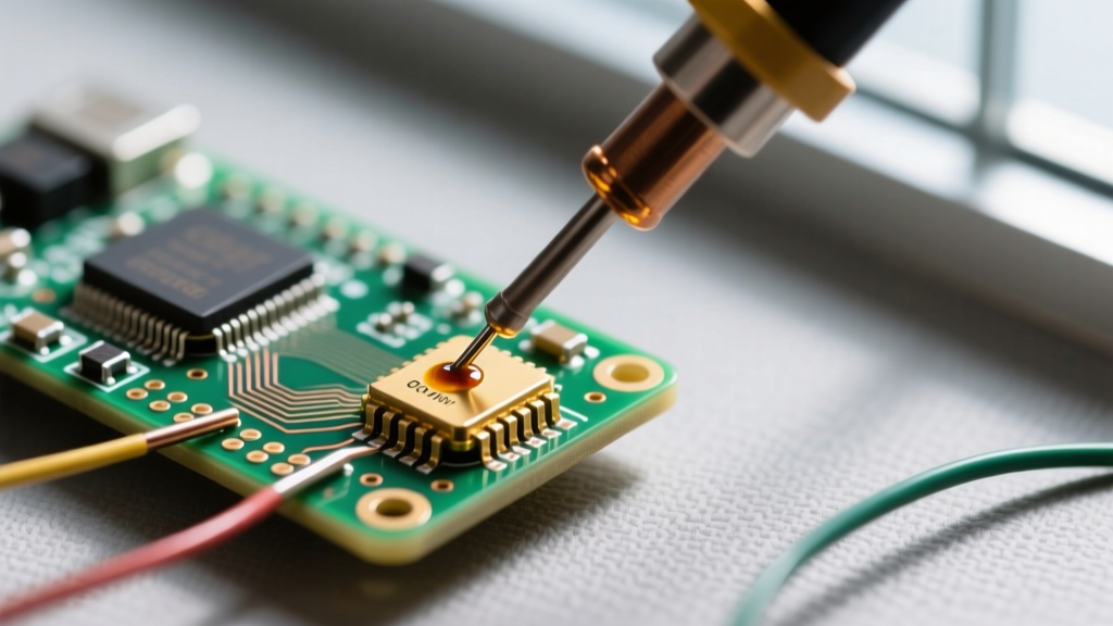
[Camera fades in on a 100x macro shot of a chisel soldering iron tip meeting a copper through-hole pad. A thin bead of molten solder wicks perfectly into the barrel.]
Welcome to this visual masterclass on choosing and utilizing the right pcb soldering wire for your electronics projects. Whether you are assembling a high-density SMD breakout board or wiring heavy-gauge power connectors to a motor controller, the physical characteristics of your solder wire dictate the success of your joint. Many hobbyists and even seasoned technicians treat solder as a generic commodity. In reality, the alloy composition, flux core percentage, and wire diameter are precision-engineered variables. In this video-style guide, we will break down the metallurgy, geometry, and chemistry of pcb soldering wire, giving you the exact specifications needed to achieve IPC-compliant joints on the first attempt.
Scene 1: The Macro Lens — Decoding Wire Diameters
[On-screen graphic: Three spools of solder appear, labeled 0.015", 0.031", and 0.050". A caliper measures each in slow motion.]
Feeding too much solder is the leading cause of bridged pads and sloppy fillets. The diameter of your pcb soldering wire must match the thermal mass and physical footprint of the component you are attaching. Using a 1.0mm wire on an 0603 SMD resistor will instantly flood the pad, while using 0.3mm wire on a 12AWG power lug will starve the joint, leading to a cold, high-resistance connection.
| Wire Diameter (Inch / mm) | Best Visual Application | Typical Component Targets |
|---|---|---|
| 0.015" (0.38mm) | Micro-SMD & Fine Pitch | 0402, 0603, 0805 SMDs, QFN pins, 0.5mm pitch ICs |
| 0.020" (0.50mm) | Standard SMD & Small THT | 1206 SMDs, SOIC chips, small signal diodes, 1/8W resistors |
| 0.031" (0.80mm) | General Purpose THT | Standard DIP ICs, electrolytic capacitors, 1/4W resistors, pin headers |
| 0.050" (1.27mm) | Heavy Power & Lugs | XT60 connectors, heavy gauge wire tinning, large ground plane vias |
[Director's Note:] For mixed-technology boards, keep a spool of 0.020" and 0.031" on your bench. Switching diameters takes seconds, but it saves minutes of cleanup with solder wick later.
Scene 2: Metallurgy Close-Up — Leaded vs. Lead-Free Alloys
[Split Screen: Left side shows Sn63/Pb37 melting instantly into a shiny puddle at 350°C. Right side shows SAC305 requiring 385°C, exhibiting a slightly duller, grainier solidification phase.]
The alloy you choose dictates your iron temperature, wetting speed, and joint reliability. Let us look at the two industry titans.
The Gold Standard: Sn63/Pb37 (Eutectic)
Composed of 63% Tin and 37% Lead, this eutectic alloy has a sharp melting point of exactly 183°C (361°F). It transitions from solid to liquid instantly, with no plastic (semi-solid) phase. This eliminates the risk of disturbing the joint during cooling, which causes micro-fractures. A 1lb spool of Kester 245 Sn63/Pb37 typically costs around $35 to $40 and remains the undisputed champion for hobbyists, prototyping, and aerospace repair where lead restrictions do not apply.
The RoHS Challenger: SAC305 (Lead-Free)
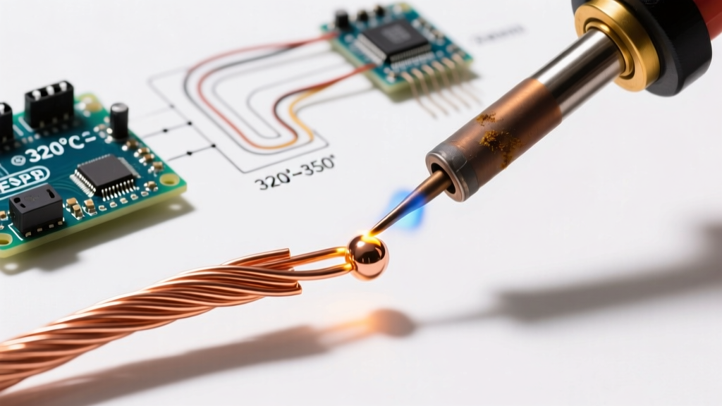
SAC305 (96.5% Tin, 3.0% Silver, 0.5% Copper) melts at a higher 217°C to 220°C. Because it is not eutectic, it has a pasty range. You must hold the iron steady until the joint fully solidifies. SAC305 requires higher iron temperatures (typically 360°C to 390°C) and aggressive flux to overcome the tin-oxide layer that forms rapidly at high heat. Expect to pay $60 to $75 for a 1lb spool of Kester 275 SAC305. Use this only when manufacturing commercial products requiring RoHS compliance.
Scene 3: The Core Cross-Section — Flux Chemistry
[Animation: A cross-section of a solder wire reveals a hollow center filled with amber-colored resin. As heat is applied, the resin boils out, pushing away black copper oxide.]
Flux is the unsung hero of the pcb soldering wire ecosystem. Without it, molten solder will ball up and refuse to wet the pad. The industry standard for electronics is Rosin-based flux, categorized into three main types:
- Type R (Rosin): Pure rosin. Extremely mild, leaves a safe, non-conductive residue. Best for highly sensitive RF circuits where residue could alter impedance.
- Type RMA (Rosin Mildly Activated): Contains slight chemical activators to clean mild oxidation. The standard for 90% of general electronics work. Kester 44 is a legendary RMA wire.
- Type RA (Rosin Activated): Highly active acids that strip heavy oxidation rapidly. Leaves a corrosive residue that must be cleaned with isopropyl alcohol or a dedicated PCB wash.
Visual Warning: Never use plumbing solder (acid core) for PCBs. The zinc chloride core will eat through your copper traces within weeks, causing catastrophic short circuits. Always verify your spool explicitly states 'Electronics Grade' or 'Rosin Core'.
Scene 4: Frame-by-Frame Execution — The 4-Second Rule
[POV Camera: Looking over the technician's shoulder. A Hakko FX-888D is set to 350°C. A timer appears in the corner of the screen.]
Even the best pcb soldering wire will fail if the thermal transfer is mismanaged. Follow this exact sequence for a flawless through-hole joint:
- 0.0s - 1.0s (Pre-Heat): Touch the flat face of your chisel or bevel tip to the intersection of the component lead and the copper pad. Heat both surfaces simultaneously. Do NOT touch the solder to the iron yet.
- 1.0s - 2.0s (Feed): Feed the pcb soldering wire into the pad, not the iron tip. The flux will activate, bubbling slightly and releasing a plume of white smoke. The solder will flash-liquid and wick up the lead via capillary action.
- 2.0s - 2.5s (Form the Fillet): Pull the wire away while keeping the iron in place for half a second longer. This allows the flux to fully degas and the solder to settle into a smooth, concave volcano shape.
- 2.5s - 3.5s (Retract & Cool): Remove the iron at a 45-degree angle. Let the joint cool naturally for 2 seconds. Do not blow on it; rapid cooling causes thermal shock and dull, fractured joints.
[B-Roll: Slow motion comparison of a perfect concave fillet vs. a convex 'blob' joint caused by feeding solder directly to the iron tip.]
Scene 5: Post-Production — Inspecting the Joint
[Camera switches to a digital microscope feed, inspecting the cooled joints under ring-light illumination.]
According to the IPC-A-610 Acceptability of Electronic Assemblies standard, a Class 2 (Standard) solder joint must exhibit a smooth, continuous, concave fillet that wets the entire pad and climbs the component lead. The solder should appear shiny (for Sn63/Pb37) or uniformly satin (for SAC305).
Troubleshooting Common Visual Defects:
| Visual Defect | Root Cause | Corrective Action |
|---|---|---|
| Cold Joint (Dull, lumpy) | Insufficient heat transfer; moving the part during the plastic phase. | Re-flow with fresh RMA flux and a higher wattage iron or pre-heater. |
| De-wetting (Solder pulls back) | Severe oxidation on the pad; iron tip is dirty. | Clean pad with fiberglass pen; tin the tip; use RA core wire. |
| Excessive Flux Residue | Wire diameter too thick for the pad; applying too much solder. | Downsize wire diameter; clean with 99% IPA and a lint-free swab. |
Director's Cut: Edge Cases & Heavy Thermal Mass
When soldering large ground plane vias or heavy power connectors, the PCB acts as a massive heat sink, pulling thermal energy away from the joint faster than a standard 60W iron can supply it. If you dwell on the pad for more than 5 seconds, you risk delaminating the copper trace.
[Visual Solution:] Upgrade to a high-wattage station like the 70W Hakko FX-951 or the 120W JBC CD-2BQE. These stations utilize active tip sensing, dumping raw wattage into the joint the millisecond a temperature drop is detected. Alternatively, use a PCB pre-heater set to 100°C to elevate the baseline temperature of the board, allowing your pcb soldering wire to flow effortlessly without scorching the flux.
Final Credits
Mastering pcb soldering wire is about understanding the physical limits of your materials. By matching your wire diameter to the component, selecting the correct eutectic or lead-free alloy, and respecting the chemistry of the flux core, you transform a chaotic melting process into a precise, repeatable science. For further visual practice and foundational techniques, refer to the excellent SparkFun through-hole soldering tutorial.
[Camera pulls back to a wide shot of a clean, well-organized workbench. The soldering iron is safely holstered. Fade to black.]