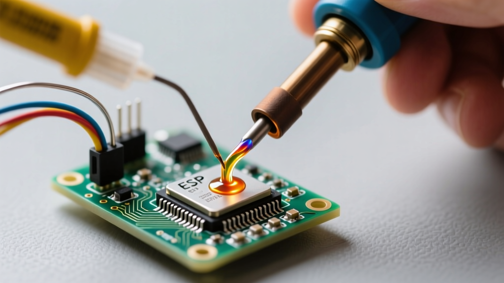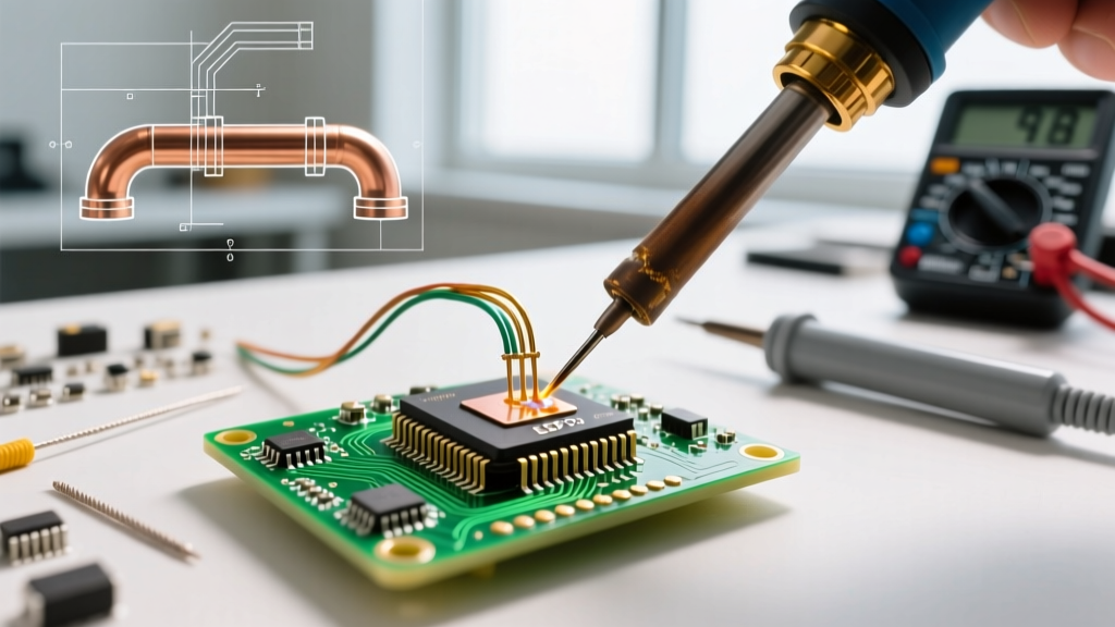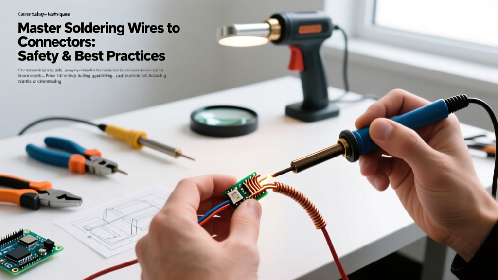

Soldering wires to connectors is a foundational skill in electronics, aviation, automotive, and DIY robotics. However, the difference between a reliable, field-proof connection and a catastrophic failure often comes down to adherence to strict safety protocols and best practices. Whether you are terminating 14 AWG silicone wire to Anderson Powerpole housings or attaching 24 AWG signal wires to DB9 solder cups, improper technique leads to high-resistance joints, melted housings, and dangerous short circuits.
In this comprehensive guide, we break down the exact methodologies, tooling, and safety standards required for soldering wires to connectors in 2026, drawing on IPC-A-620 wire harness requirements and aerospace-grade reliability principles.
Essential Safety Gear and Workspace Prep
Before picking up your iron, your workspace must be configured to mitigate the two primary hazards of soldering: toxic fume inhalation and thermal/electrical burns.
Fume Extraction and Respiratory Safety
Flux vapors—whether from rosin-based (RMA) or no-clean fluxes—contain colophony, a known respiratory sensitizer. Prolonged exposure can lead to occupational asthma. Furthermore, if you are still using traditional 63/37 tin-lead solder, you must manage lead particulate risk. While the primary vector for lead exposure is hand-to-mouth transfer rather than inhalation (lead vaporizes at temperatures far above standard soldering irons), maintaining strict hygiene and ventilation is non-negotiable.
- Source Capture: Use an active HEPA and carbon-filter fume extractor positioned 4 to 6 inches from the joint. The Hakko FA-400 or the higher-end Pace ARM-EVAC are industry standards.
- Ambient Ventilation: Ensure your room has positive airflow. Do not rely on a desk fan, which merely blows hazardous particulates across your face and workspace.
- Hygiene: Follow OSHA guidelines on lead exposure by washing hands with cold water and specialized lead-removal soap (like D-Lead) before eating or drinking.
Thermal and ESD Safety
Connectors often interface with sensitive microcontrollers or ESCs. An electrostatic discharge (ESD) event from an ungrounded iron tip can instantly destroy a MOSFET or MCU. Always use an ESD-safe mat and a grounded soldering station (e.g., Weller WE1010NA or Pace ADS200) with verified tip-to-ground resistance of less than 2 ohms.
Wire Preparation: The Foundation of a Reliable Joint
The most common point of failure when soldering wires to connectors occurs before the iron even touches the metal. Wire preparation dictates the mechanical and electrical integrity of the final joint.
Stripping and Strand Management
Use precision wire strippers calibrated to your exact AWG. For stranded wire, stripping too aggressively will nick the outer copper strands, reducing the wire's current-carrying capacity and creating stress fractures.
Expert Rule of Thumb: When stripping wire for a solder cup connector, the exposed copper should be exactly 1/32 inch shorter than the depth of the cup. This ensures no bare wire protrudes past the cup's rim, which could cause a short circuit or prevent the heat shrink from sealing properly.
The Art of Tinning
Never attempt to mate an untinned wire to a tinned connector cup. Both surfaces must be pre-tinned. Apply a minimal amount of high-quality flux (such as Kester 245) to the stripped wire, then introduce your solder (AIM SAC305 for lead-free, or Kester 44 for leaded). The solder should wick up the strands via capillary action, leaving a smooth, shiny, concave profile. If the wire looks bulbous or dull, you have used too much solder or the iron temperature was too low.
Execution: Soldering Techniques by Connector Type
Different connector geometries demand distinct thermal management strategies. Applying a one-size-fits-all approach will melt plastic housings or lift PCB pads.
Solder Cup Connectors (DB9, DB15, XLR, RCA)
Solder cups act as massive heat sinks. To properly solder wires to these connectors without melting the surrounding plastic insulation:
- Pre-tin the Cup: Fill the cup with a small pool of solder. Remove the iron and let it solidify.
- Position the Wire: Slide your adhesive-lined heat shrink onto the wire before this step. Insert the pre-tinned wire into the cup.
- Reflow: Apply the iron to the side of the cup (not the wire). The existing solder in the cup and on the wire will melt simultaneously.
- Hold and Cool: Hold the wire perfectly still for 3 to 5 seconds. Blowing on the joint or moving it while the solder is in its plastic (semi-solid) state will cause a cold, fractured joint.
Micro-Connectors (JST-PH, Molex PicoBlade)
When soldering wires to micro-connectors or PCB-mounted headers, the thermal mass is incredibly low. Using a 400°C chisel tip will instantly delaminate the pad or melt the nylon housing. Switch to a micro-pencil tip (e.g., Weller RT3 or TS100 TS-I tip) and drop your station temperature to 300°C–320°C for leaded solder. Use a flux pen to tack the wire in place, then apply heat for no more than 1.5 seconds per pin.
Strain Relief and Insulation Best Practices
A perfect solder joint is useless if mechanical stress fractures it a week later. According to NASA Electronic Parts and Packaging (NEPP) workmanship standards, all wire-to-terminal connections in high-reliability environments require robust strain relief.
Adhesive-Lined Heat Shrink (Dual-Wall)
Standard 2:1 polyolefin heat shrink is insufficient for connectors that will be handled, pulled, or subjected to vibration. You must use 3:1 or 4:1 dual-wall heat shrink tubing (such as 3M EPS300 or TE Connectivity RW-175).
- The Inner Layer: The inner wall is coated with a thermoplastic polyamide adhesive. When heated to roughly 120°C, this adhesive melts and flows into the interstices between the wire strands and the connector housing, creating a waterproof, structural bond.
- The Outer Layer: The outer cross-linked polyolefin shrinks tightly, providing abrasion resistance and dielectric insulation.
- Application Technique: Heat the tubing starting from the connector body and move toward the wire. This forces the melting adhesive to extrude slightly out the back edge of the tubing, confirming a complete internal seal. Wipe away excess adhesive with isopropyl alcohol while warm.
Common Failure Modes and Troubleshooting Matrix
Even experienced technicians encounter anomalies. Use this diagnostic matrix to identify and correct issues when soldering wires to connectors.
| Failure Mode | Visual / Physical Cue | Root Cause | Corrective Action |
|---|---|---|---|
| Cold Joint | Dull, grainy, or lumpy surface; joint moves slightly under pressure. | Insufficient heat transfer; wire moved during cooling phase. | Re-flow with fresh flux and higher iron mass; hold completely still until solid. |
| Wicking / Solder Creep | Solder travels up the wire insulation, making it stiff and brittle. | Excessive heat applied too long; wire stripped too far back. | Cut the wire back, re-strip, and use a lower temperature with a faster-working tip. |
| Melted Housing | Plastic connector body is warped; pins are misaligned. | Iron held against the cup for >4 seconds; tip too large for the thermal mass. | Use a smaller tip to focus heat; pre-tin both surfaces to minimize dwell time. |
| Insufficient Fill | Solder does not reach the top rim of the solder cup (Fails IPC Class 3). | Wire gauge too small for the cup; insufficient solder volume. | Use a larger wire gauge or fold the wire back on itself to increase cup fill volume. |
Tooling and Material Recommendations for 2026
The soldering landscape has evolved. With lead-free mandates expanding beyond the EU's RoHS into global commercial aerospace and automotive sectors, your tooling must handle the higher thermal demands of SAC305 (Tin/Silver/Copper) alloys.
- Soldering Stations: The Pace ADS200 and the JBC CD-2BQE offer the rapid thermal recovery required to solder heavy-gauge wires to massive connectors without dropping tip temperature. Expect to invest between $450 and $650 for a production-grade setup.
- Solder Wire: For hobbyist and non-RoHS applications, 63/37 eutectic solder (0.031 inch diameter) remains the gold standard due to its sharp melting point. For commercial 2026 compliance, use 0.020 inch SAC305 with a no-clean flux core (e.g., Kester 275).
- Flux: Keep a syringe of Amtech NC-559-V2-TF or a bottle of Kester 951 liquid flux on hand. Additional flux is the secret to conquering stubborn, oxidized connector pins.
Final Thoughts on Reliability
Mastering the art of soldering wires to connectors is less about raw speed and more about disciplined preparation and thermal control. By prioritizing workspace safety, adhering to strict wire-prep protocols, and utilizing dual-wall adhesive heat shrink, you ensure that your harnesses will survive the harshest real-world conditions. Whether you are building a custom drone power distribution board or repairing vintage audio equipment, these best practices will yield joints that are mechanically rugged, electrically flawless, and visually professional.