
The 'Cold Soldering' Terminology Paradox
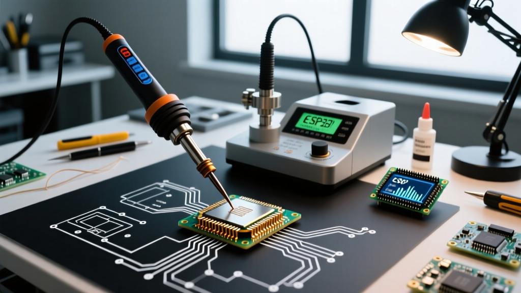
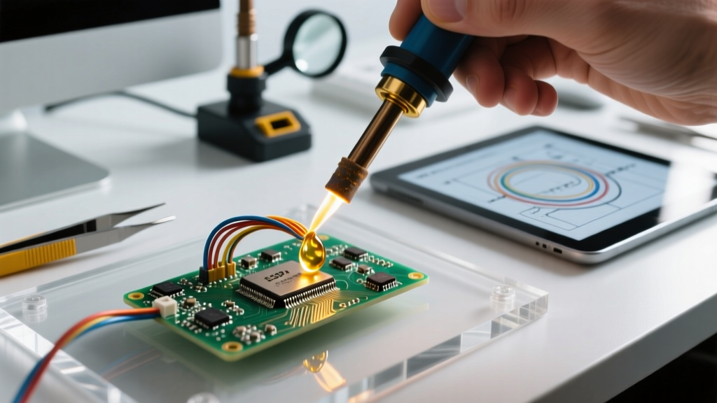
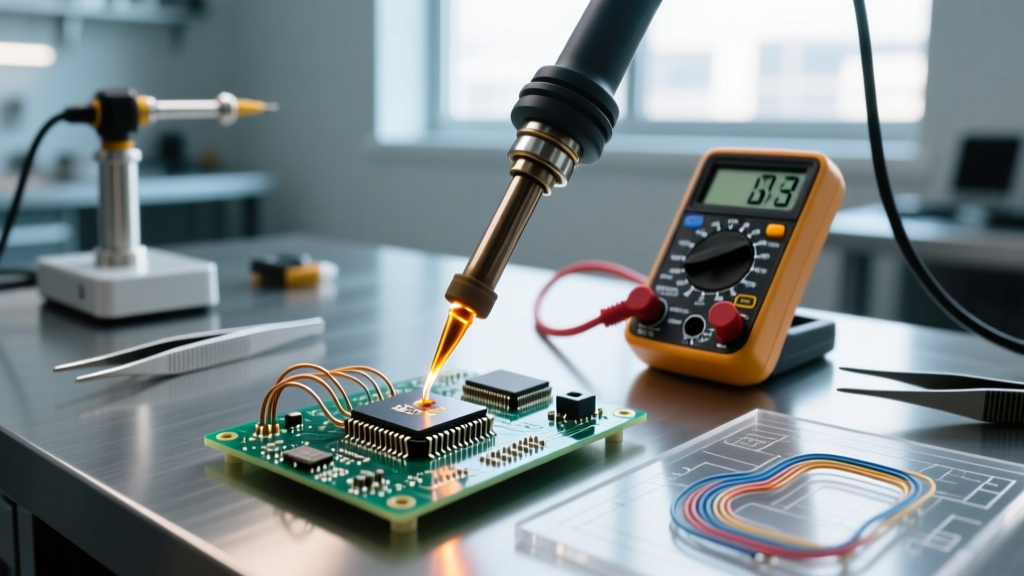
In professional electronics manufacturing, a 'cold solder joint' is a critical defect—a brittle, high-resistance connection caused by insufficient thermal energy during reflow. However, in the DIY, repair, and prototyping communities, the term cold soldering tool has evolved to describe an entirely different concept: methods and materials that bypass the 350°C+ heat of traditional soldering irons to protect heat-sensitive components.
As of 2026, the miniaturization of wearable tech, flexible printed circuits (FPCs), and vintage electronics restoration has made thermal management a primary concern. Exposing a flexible polyimide substrate or a vintage bakelite housing to a standard SAC305 (Silver/Copper/Tin) soldering profile will result in delamination, pad cratering, or melting. To solve this, engineers utilize two primary 'cold' or low-heat alternatives: Bismuth-based low-temperature solder pastes and Conductive Silver Epoxies.
This tutorial provides a deep-dive, step-by-step guide to utilizing both methods, complete with metallurgical insights, exact thermal profiles, and failure-mode troubleshooting.
Material Comparison: Bismuth Paste vs. Silver Epoxy
Before selecting your cold soldering tool, you must understand the physical limitations of low-heat alternatives. Neither method replaces standard tin-lead or lead-free solder for high-stress, high-current applications.
| Method | Material / Alloy | Melting / Cure Point | Tensile Strength | Volume Resistivity | Best Application |
|---|---|---|---|---|---|
| Low-Temp Paste | Bi58/Sn42 (Bismuth/Tin) | 138°C (280°F) | ~5,500 PSI | 14 µΩ·cm | Flex PCBs, RF shields, LED strips |
| Silver Epoxy | Silver-filled Bisphenol-A | Cures at 24°C / 80°C | ~2,900 PSI | 6 µΩ·cm | Jumpers, EMI shielding, heat-intolerant substrates |
| Standard Solder | SAC305 (Lead-Free) | 217°C (422°F) | ~8,500 PSI | 12 µΩ·cm | General purpose, high-reliability SMD |
Essential Tooling & 2026 Material Costs
To execute these techniques properly, you need precision application tools. Guesswork with a toothpick will yield high-resistance joints.
- Low-Temp Solder Paste: Chip Quik SMDLTLFP (Bi58/Sn42 with No-Clean ROL0 flux). Current retail price is approximately $28 for a 10cc syringe.
- Conductive Epoxy: MG Chemicals 8331 Silver Conductive Epoxy. Retail price is roughly $48 for a 7mL dual-cartridge.
- Dispensing Needles: 22-gauge (0.41mm inner diameter) Luer-lock stainless steel tips.
- Thermal Control: A digital hot air rework station (e.g., Hakko FR-810B or a calibrated 858D clone) with a narrow nozzle.
- Prep Solvents: 99.9% Isopropyl Alcohol (IPA) and lint-free Kimwipes.
Step-by-Step: Low-Temp Bismuth Soldering (The 'Warm' Method)
Bismuth solder melts at 138°C, allowing you to reflow components without damaging surrounding heat-sensitive plastics or previously soldered joints. According to the Indium Corporation's Low-Temperature Solder Guide, Bi58/Sn42 is ideal for step-soldering processes where secondary reflows must not disturb primary joints.
Step 1: Surface Preparation and Masking
Clean the PCB pads with 99.9% IPA. Apply Kapton tape (polyimide film) around the work area. Bismuth paste has high surface tension when molten, but flux splatter can still contaminate adjacent RF traces or optical sensors.
Step 2: Precision Paste Dispensing
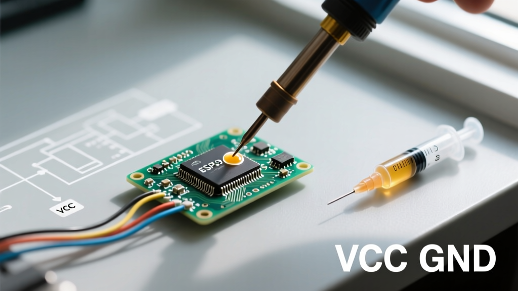
Attach a 22-gauge needle to the Chip Quik syringe. Depress the plunger until a bead exactly half the size of the target SMD pad emerges. For 0402 or 0603 components, a single micro-dot on each pad is sufficient. Do not bridge the gap between pads; the flux's surface tension will pull the molten solder to the copper during reflow.
Step 3: Thermal Profiling (The Critical Phase)
Set your hot air station to 160°C with an airflow rate of 30%. High airflow will blow the lightweight SMD component off the pad before the solder wets.
- Hold the nozzle 15mm above the component.
- Ramp the temperature for 30 seconds to allow the flux to activate and outgas.
- Lower the nozzle to 8mm. Watch for the paste to transition from dull gray to a shiny, mirror-like liquid (the 138°C liquidus point).
- Once the solder flashes to a mirror finish, maintain heat for exactly 10 seconds to ensure intermetallic compound (IMC) formation between the tin and the copper pad.
Expert Warning: Never use compressed air or blow on a Bismuth joint to cool it. Bi58/Sn42 is highly susceptible to thermomechanical shock. Rapid cooling induces micro-cracking in the crystalline structure, resulting in a joint that passes a visual inspection but fails under minimal vibration. Allow it to cool naturally at room temperature.
Step-by-Step: Conductive Silver Epoxy (The True 'Cold' Method)
When even 138°C is too hot—such as when repairing flexible wearable sensors, piezoelectric films, or vintage paper-based circuit boards—conductive silver epoxy is the ultimate cold soldering tool. It relies on a polymer curing process rather than metallurgical wetting. The IPC J-STD-001 standard notes that while conductive adhesives lack the self-aligning surface tension of molten solder, they are indispensable for thermally intolerant substrates.
Step 1: Mechanical Abrasion
Unlike solder, epoxy does not chemically strip oxidation via flux. You must mechanically expose bare copper or silver. Use a fiberglass scratch pen or 2000-grit sandpaper to lightly abrade the repair pads until they are bright and shiny. Clean immediately with IPA to prevent flash oxidation.
Step 2: Mixing and Dispensing
If using a two-part MG Chemicals 8331 system, mix the resin and hardener in a strict 1:1 volume ratio on a glass slide. Mix for 60 seconds until the color is uniformly dark gray. For dual-cartridge syringes, the static mixer nozzle handles this automatically. Dispense a microscopic bead onto the pad.
Step 3: Component Placement and Curing
Place the component into the epoxy bead using precision tweezers. Apply slight downward pressure to squeeze out excess epoxy and ensure the silver flakes make physical contact with both the component lead and the PCB pad.
- Room Temperature Cure: 24 hours (Yields maximum tensile strength).
- Accelerated Cure: 15 minutes at 80°C (Only if the substrate can tolerate mild warmth).
Advanced Failure Modes & Edge Cases
Understanding why cold soldering tools fail is just as important as knowing how to use them. Troubleshooting these methods requires looking at material science edge cases.
Thermomechanical Fatigue in Bismuth Alloys
Bismuth solder is notoriously brittle. If you use Bi58/Sn42 to attach a heavy component (like a large electrolytic capacitor or a shielded inductor) to a board that experiences physical flexing, the joint will fracture. The bismuth crystalline lattice cannot absorb mechanical shear stress. Solution: Always apply a non-conductive underfill or UV-curable conformal coating (e.g., Loctite 3108) around the base of components soldered with low-temp paste to transfer mechanical stress away from the brittle solder joint.
Contact Resistance Drift in Epoxies
Conductive epoxies do not form an intermetallic bond; they rely on physical pressure between silver flakes. Over time, in high-humidity environments, the polymer matrix can absorb moisture and swell microscopically. This swelling pushes the silver flakes apart, causing the volume resistivity to drift upward, leading to voltage drops in sensitive analog circuits. Solution: Never use silver epoxy for high-current power rails (anything exceeding 500mA) or precision analog sensor traces. Restrict its use to digital logic jumpers, EMI grounding straps, and low-current signal repairs.
Summary
Mastering the use of a cold soldering tool expands your repair capabilities into realms where traditional irons would cause catastrophic damage. By understanding the metallurgical brittleness of Bismuth pastes and the mechanical limitations of Silver Epoxies, you can safely restore flexible wearables, vintage electronics, and densely packed RF modules. Always prioritize surface preparation, respect the thermal profiles, and select the material based on the electrical and mechanical demands of the specific circuit.
For further reading on advanced adhesive applications in electronics, refer to the MG Chemicals Conductive Epoxies Technical Documentation for specific cure schedules and substrate compatibility charts.