
The Metallurgical Divide: Beyond the 450°C Threshold
When advanced makers and electrical engineers evaluate brazing versus soldering, the conversation often stagnates at the American Welding Society's (AWS) arbitrary 840°F (450°C) temperature threshold. While this thermal boundary is technically accurate—soldering occurs below it, brazing above—it entirely misses the profound metallurgical differences that dictate joint longevity, electrical conductivity, and mechanical shear strength in high-stress applications.
As of 2026, with the rise of high-discharge EV battery builds and DIY RF amplifiers, understanding the atomic behavior of filler metals is no longer optional. This guide dissects the thermodynamics, equipment dynamics, and failure modes of both processes to help you engineer joints that survive extreme thermal cycling and mechanical vibration.
Atomic Bonding: IMC Layers vs. Solid-State Diffusion
Intermetallic Compounds (IMC) in Soldering
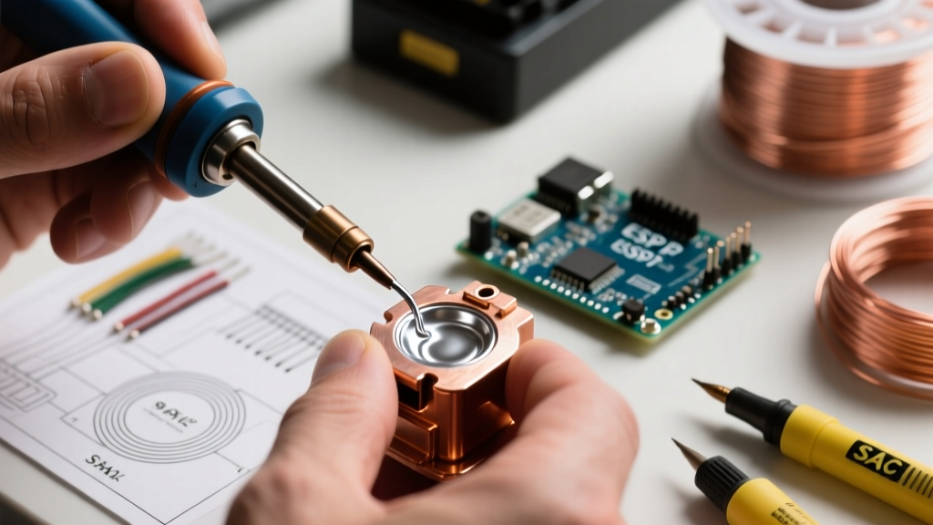
Soldering does not melt the base metal. Instead, it relies on wetting and the formation of an Intermetallic Compound (IMC) layer. When using a standard SAC305 (96.5% Sn, 3.0% Ag, 0.5% Cu) lead-free alloy on a copper substrate, the tin reacts with the copper to form a Cu6Sn5 layer. According to IPC standards, a pristine IMC layer should be between 1 to 3 micrometers thick.
If your thermal profile is flawed—say, dwelling a 70W iron tip at 380°C for more than 4 seconds—the IMC layer overgrows into Cu3Sn. This secondary phase is highly brittle and acts as a micro-fracture initiation site under mechanical shock. This is why precision thermal control is non-negotiable in advanced electronics assembly.
Solid-State Diffusion and Capillary Flow in Brazing
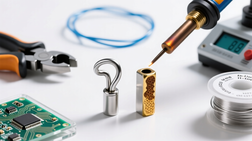
Brazing operates on principles of solid-state diffusion and capillary action. Unlike solder, which merely adheres to the surface via IMC bonding, high-temperature brazing alloys (like silver-based BAg-24) actually diffuse into the grain boundaries of the base metal. As detailed by the filler metal experts at Lucas-Milhaupt, successful capillary brazing requires meticulous joint clearance—typically 0.001 to 0.005 inches (0.025 to 0.127 mm) at the brazing temperature, not room temperature. This accounts for the differential thermal expansion of the base metals. If the gap is too wide, capillary forces fail, and the joint relies solely on the weaker tensile strength of the bulk filler metal.
Thermal Profiling and Equipment Dynamics
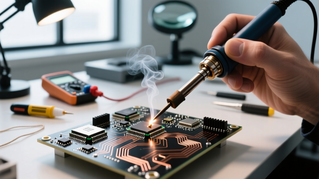
Precision Soldering Station Architecture
For heavy-ground-plane PCB work or thick copper wire tinning, thermal recovery is paramount. The Hakko FX-951 ($350) utilizes a composite cartridge tip (T18 series) where the ceramic heating element is embedded directly inside the tip, minimizing thermal resistance. Conversely, older architectures separate the heater and tip, creating a thermal bottleneck. When executing continuous solder joints on 8 AWG silicone wire, the FX-951 maintains a stable 350°C delta, whereas separated-element irons suffer a 40°C temperature drop, leading to cold joints and incomplete wetting.
Brazing Torch and Induction Topologies
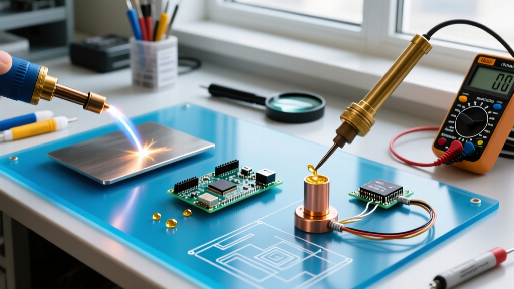
Brazing demands rapid, localized heat input to prevent the flux from burning off before the filler metal reaches its liquidus state. For oxy-acetylene setups, the Smith AW1A ($450) with a #3 or #4 rosebud tip provides a broad, reducing flame (slightly fuel-rich) that prevents oxidation of the copper substrate.
For production-level DIY or repetitive busbar assembly, induction brazing is vastly superior. An entry-level Ambrell or GHF induction heater ($4,500 - $8,000 in 2026) generates eddy currents directly within the copper workpiece, heating the joint to 1300°F in under 3 seconds without oxidizing the surrounding area. This requires boron-modified white flux to protect the silver alloy from atmospheric contamination at extreme temperatures.
Joint Mechanics: Shear, Tensile, and Fatigue Limits
To truly master the decision of brazing versus soldering, one must analyze the mechanical limits of the resulting alloy matrix. The American Welding Society (AWS) classifies these alloys based on strict shear and tensile metrics. Below is a comparative matrix of common alloys used in advanced electrical and mechanical DIY builds.
| Alloy Designation | Composition | Solidus / Liquidus | Tensile Strength (PSI) | Primary Application |
|---|---|---|---|---|
| Sn63/Pb37 | 63% Sn, 37% Pb | 361°F / 361°F (Eutectic) | 6,250 | General PCB, low-stress wiring |
| SAC305 | 96.5% Sn, 3% Ag, 0.5% Cu | 423°F / 441°F | 8,500 | RoHS electronics, high-reliability SMD |
| BCuP-5 (15% Ag) | 80% Cu, 15% Ag, 5% P | 1190°F / 1495°F | 70,000 | Copper-to-copper busbars, HVAC, motor windings |
| BAg-24 (50% Ag) | 50% Ag, 34% Cu, 16% Zn | 1225°F / 1425°F | 75,000 | Dissimilar metals, steel-to-copper, high vibration |
Failure Mode Analysis: Why Joints Fail in the Field
Understanding how joints fail allows you to engineer against them. Here are the three most common failure modes in advanced DIY electrical builds:
- Thermal Creep (Soldering): Solder alloys, particularly tin-lead, operate at a high homologous temperature even at room temperature. Under constant mechanical load (like a heavy suspended capacitor), the solder will slowly deform or 'creep' over months, eventually breaking the electrical connection. Brazed joints do not exhibit creep at standard operating temperatures.
- CTE Mismatch Fatigue (Soldering): When soldering large silicon dies or ceramic substrates to copper heat sinks, the Coefficient of Thermal Expansion (CTE) mismatch causes shear stress during power cycling. This leads to micro-cracking in the solder fillet. Advanced builders mitigate this by using stepped heat sinks or compliant indium-based solders.
- Galvanic Corrosion (Brazing & Soldering): When joining dissimilar metals (e.g., aluminum to copper) in humid environments, the filler metal can act as an anode or cathode, accelerating galvanic corrosion. Silver brazing alloys are generally more noble than copper, meaning the copper will sacrifice itself if the joint is exposed to electrolytes. Proper encapsulation with marine-grade heat shrink or conformal coating is mandatory.
Advanced Decision Matrix: Real-World Scenarios
Scenario 1: High-Current EV Battery Busbars
When building custom 48V or 96V battery packs using 21700 cells and thick 1/4-inch copper busbars, brazing is the only viable thermal joining method. If you attempt to solder these joints, the massive thermal mass will require prolonged heat application, destroying the cell's internal separator. Furthermore, under a continuous 150A load, I²R heating will raise the busbar temperature. A solder joint will suffer from thermal creep and eventual meltdown. Using a BCuP-5 (copper-phosphorus) brazing alloy with induction heating creates a joint with 70,000 PSI tensile strength that will easily outlast the battery cells themselves.
Scenario 2: RF Amplifier Shielding and Waveguides
For ham radio operators or SDR (Software Defined Radio) builders constructing copper enclosures for 2.4GHz or 5.8GHz RF amplifiers, silver soldering (hard soldering/brazing) is preferred over soft soldering. Soft solder has higher RF resistance at microwave frequencies due to the skin effect and the specific conductivity of tin. A BAg-24 silver braze provides superior conductivity and creates a hermetic seal that prevents RF leakage. The joint clearance must be kept under 0.002 inches to ensure the silver alloy is drawn entirely through the seam via capillary action, leaving no internal voids that could cause multipath interference inside the waveguide.
Expert Insight: The phrase 'silver solder' is a notorious industry misnomer. True soldering melts below 450°C. Silver-bearing alloys that melt above 1100°F are technically brazing alloys. Always check the AWS classification (BAg vs. Sn) rather than relying on hardware store nomenclature when engineering critical joints.
Scenario 3: Precision Thermocouple and Sensor Wiring
When attaching fine-gauge (30 AWG) Type K or Type T thermocouple wires to stainless steel or Inconel sheaths, soft soldering is impossible due to the lack of wetting on high-nickel alloys without highly corrosive acid fluxes. Here, micro-torch brazing using a specialized nickel-based or high-silver paste (applied via syringe) ensures a robust metallurgical bond that can withstand the 500°C+ ambient temperatures of an industrial kiln or exhaust manifold without the joint degrading.
Conclusion
The debate of brazing versus soldering is not about which process is universally 'better,' but rather which metallurgical mechanism aligns with your thermal, mechanical, and electrical constraints. By mastering IMC layer control in soldering and capillary clearance dynamics in brazing, you elevate your builds from fragile prototypes to industrial-grade systems capable of surviving the harshest real-world environments.