
The Metallurgical Boundaries of Metal Joining
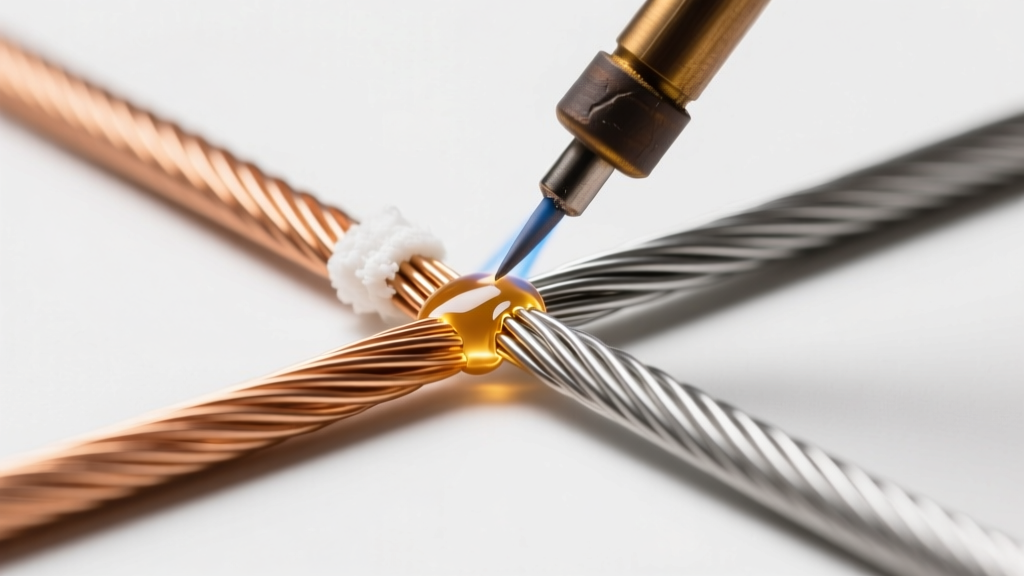
When evaluating brazing vs welding vs soldering, the fundamental differentiator is temperature and whether the base metal melts. As of 2026, DIYers and professionals alike must choose the correct thermal process based on joint strength requirements, base material metallurgy, and thermal distortion limits. A poorly chosen joining method leads to catastrophic failure modes like cold laps, intergranular penetration, or severe heat-affected zone (HAZ) warping.
This step-by-step tutorial breaks down the exact procedures, filler metal classifications, and thermal thresholds for all three processes, providing actionable frameworks for electrical, plumbing, and structural applications.
Decision Matrix: Which Process to Choose?
Before striking an arc or lighting a torch, consult this comparative matrix to align your project requirements with the correct metallurgical process.
| Parameter | Soldering | Brazing | Welding |
|---|---|---|---|
| Temperature Threshold | Below 450°C (842°F) | Above 450°C (842°F) | Above base metal melting point |
| Base Metal Melting | No | No | Yes |
| Joint Mechanism | Capillary action / Adhesion | Capillary action / Alloying | Coalescence / Fusion |
| Tensile Strength | Low (Up to 15,000 psi) | Medium-High (Up to 60,000 psi) | Very High (Matches base metal) |
| Primary Applications | PCBs, low-pressure plumbing | HVAC, bicycle frames, jewelry | Structural steel, automotive, pipelines |
Process 1: Soldering (Below 450°C)
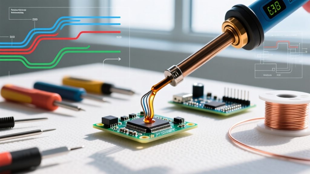
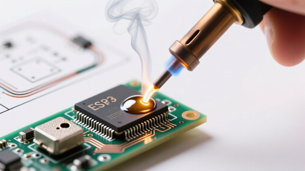
Soldering relies entirely on capillary action and metallurgical wetting without altering the base metal's structural integrity. In 2026, lead-free alloys like SAC305 (Sn96.5/Ag3.0/Cu0.5) dominate electronics, while 95/5 Tin-Antimony remains the standard for potable plumbing.
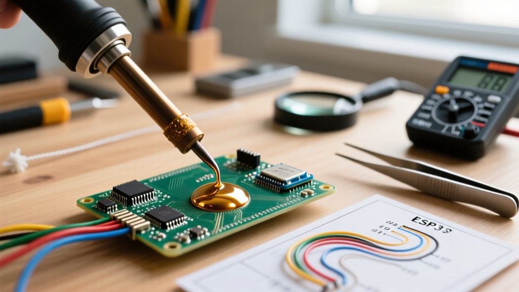
Step-by-Step Electronics Soldering Workflow
Equipment: Weller WE1010NA digital station, Kester 245 63/37 rosin-core wire (0.031" diameter), brass sponge.
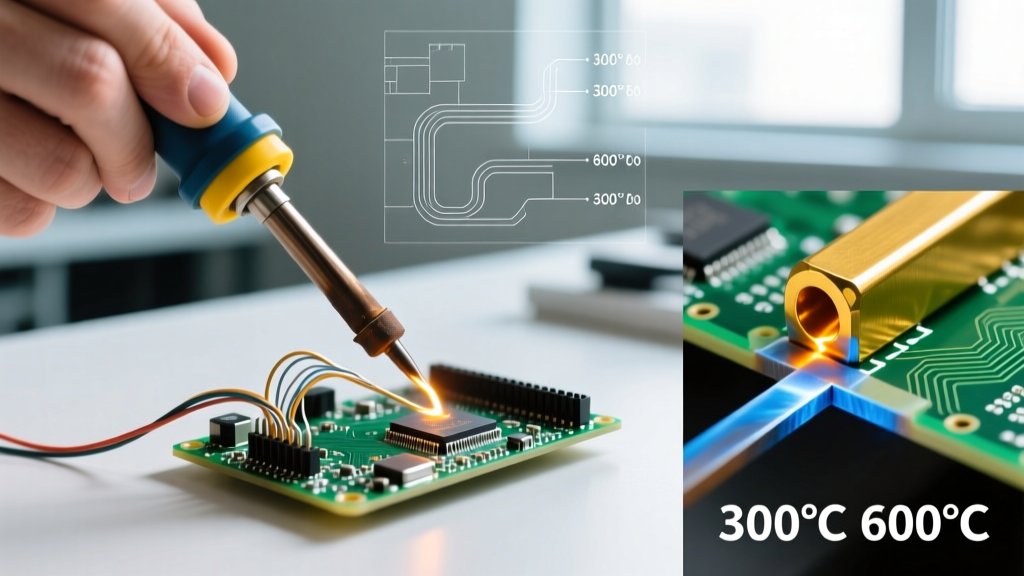
- Thermal Profiling: Set the iron to 350°C (662°F) for standard Sn63/Pb37 eutectic solder. If using SAC305 lead-free, increase to 380°C (716°F) to overcome the higher 217°C melting point and ensure proper wetting.
- Tinning the Tip: Apply a generous amount of flux-core solder to the iron tip immediately upon heating. This creates a thermal bridge and prevents oxidation.
- Simultaneous Heating: Touch the iron to both the component lead and the PCB pad simultaneously for exactly 1.5 to 2 seconds. Never feed solder directly onto the iron tip and attempt to carry it to the joint.
- Capillary Feed: Introduce the solder wire to the joint, not the iron. Once the flux activates (visible bubbling), the solder will wick into the plated through-hole via capillary action.
- Inspection: A proper joint exhibits a concave fillet with a shiny finish (for leaded) or a slightly dull, grainy finish (for lead-free SAC alloys, per IPC J-STD-001 standards).
Pro Tip: For heavy ground planes, use a chisel tip (e.g., Weller ETA) to maximize surface area contact. If the solder beads up and refuses to flow, you are experiencing a 'cold joint' due to insufficient thermal mass transfer. Increase dwell time, not necessarily temperature.
Process 2: Brazing (Above 450°C)
Brazing produces significantly stronger joints than soldering by utilizing higher temperatures and specialized filler metals classified by the American Welding Society (AWS) under the A5.8 specification. The base metal does not melt, but the filler metal alloys with the base metal surface.
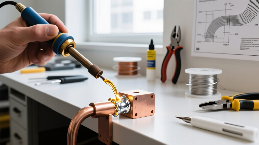
Step-by-Step HVAC Copper Brazing Workflow
Equipment: Sievert TurboTorch, Harris Stay-Silv 15 (15% Silver, Copper, Phosphorus), Stay-Silv Black Flux.
- Mechanical & Chemical Prep: Clean the copper tubing with 120-grit emery cloth. Wipe with isopropyl alcohol to remove oils. Capillary clearance must be strictly maintained between 0.025mm and 0.125mm (0.001" to 0.005").
- Flux Application: While BCuP alloys (copper-phosphorus) are self-fluxing on pure copper, applying a thin coat of borax-based Black Flux is mandatory if brazing copper to brass or steel to prevent refractory oxide formation.
- Preheating: Use a neutral oxy-acetylene flame. Heat the base metal broadly, keeping the flame moving. Do not concentrate heat on the joint seam. The goal is to bring the entire fitting to a dull cherry red (approx. 650°C / 1200°F).
- Filler Introduction: Remove the flame and touch the Stay-Silv 15 rod to the joint. If the base metal is hot enough, the rod will instantly melt and be drawn deep into the fitting via capillary action.
- Quenching & Cleaning: Allow the joint to air cool to a black heat, then quench with a damp rag to thermally shock and flake off the glass-like flux residue. Wire brush the remainder.
Process 3: Welding (Base Metal Fusion)
Welding achieves the highest structural integrity by melting the base metals and adding a compatible filler to create a unified grain structure. According to extensive technical resources from the Lincoln Electric education library, Gas Tungsten Arc Welding (GTAW/TIG) offers the most precise control for thin-gauge and critical structural joints.
Step-by-Step TIG Welding (GTAW) for Mild Steel
Equipment: Everlast PowerTIG 200DV, 2% Ceriated Tungsten (Gray, 3/32"), ER70S-6 filler rod, 100% Argon shielding gas.
- Joint Beveling: For steel thicker than 3mm (1/8"), grind a 60-degree V-groove bevel. This ensures full penetration at the root of the joint.
- Shielding Gas Setup: Set the Argon flowmeter to 15-20 Cubic Feet per Hour (CFH). Ensure your post-flow timer is set to at least 5 seconds to protect the cooling tungsten and weld puddle from atmospheric contamination.
- Arc Initiation: Position the tungsten 2mm from the workpiece. Use the high-frequency start to initiate the arc without touching the metal. Establish a molten puddle (the 'keyhole') at the leading edge of the joint.
- Dabbing Technique: Move the torch forward by 2mm, then dip the ER70S-6 rod into the leading edge of the puddle. Withdraw the rod, move forward, and repeat. Maintain a tight arc length (1-2mm).
- Crater Fill: At the end of the weld, do not simply release the trigger. Use the machine's crater fill function or manually pulse the foot pedal down to zero to prevent a star-crack at the termination point.
Critical Failure Modes & Edge Cases
Understanding why joints fail is just as important as knowing how to make them. Here are the most common edge cases encountered in 2026 fabrication environments:
- Intergranular Penetration (Brazing Steel): If you attempt to braze high-carbon steel or hardened tool steel with a copper-based filler (like brass), the liquid copper will penetrate the steel's grain boundaries, causing immediate, catastrophic cracking under stress. Always use silver-based (BAg) fillers for steel.
- Porosity (Welding): Caused by atmospheric nitrogen and oxygen entering the weld pool. In TIG welding, this is almost always a result of insufficient Argon coverage, a contaminated base metal (mill scale or rust), or a draft in the shop blowing the shielding gas away.
- Flux Inclusions (Soldering/Brazing): If the joint is not heated evenly, the flux may melt and flow into the capillary space before the base metal is hot enough to melt the filler. This traps non-metallic slag inside the joint, resulting in a weak, leaky connection. Always heat the base metal first.
Cost & Equipment Considerations for 2026
When budgeting for a metal-joining workstation, the capital expenditure varies wildly across these three disciplines. A high-end digital soldering station (like the JBC CD-2BE) will cost around $600, while a complete prosumer TIG welding setup (machine, gas cylinder, and PPE) easily exceeds $1,500. Brazing sits in the middle; a professional oxy-acetylene torch kit and a pound of 15% silver brazing rod will cost approximately $400 to $500. For further technical specifications on joint design and filler metal selection, consult the Copper Development Association guidelines for plumbing and HVAC applications.
Final Verdict
Choosing between brazing, welding, and soldering is not a matter of preference, but of metallurgical necessity. Use soldering for electrical continuity and low-stress plumbing. Rely on brazing when you need high tensile strength without warping thin base metals or altering their heat treatment. Reserve welding for maximum structural fusion where the joint must match or exceed the base metal's yield strength. By strictly adhering to the thermal profiles and preparation steps outlined above, you will achieve flawless, code-compliant joints every time.