
The Metallurgy of a Reliable Wire Joint
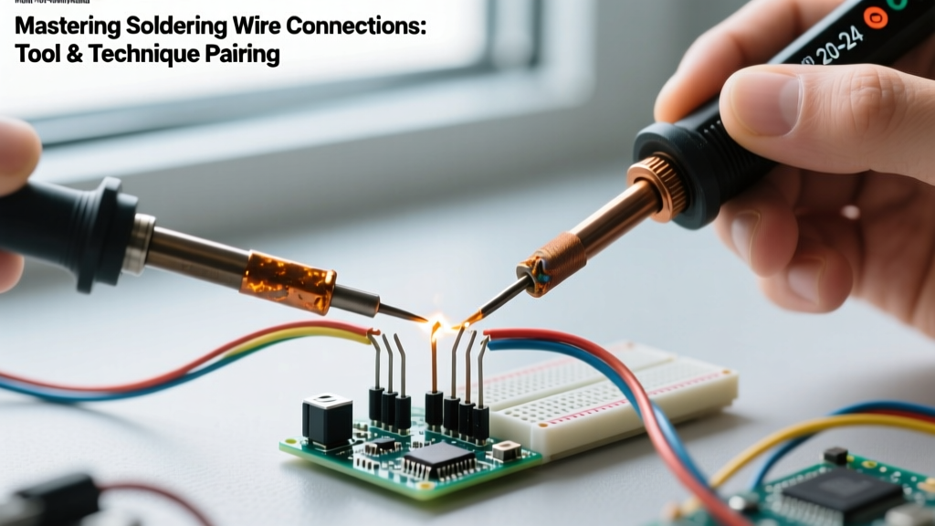
Creating a permanent, low-resistance electrical bond between two copper conductors requires more than just melting metal. When IPC J-STD-001 standards dictate the requirements for soldered electrical assemblies, they emphasize metallurgical wetting over simple mechanical adhesion. Soldering wire connections successfully means achieving a localized alloy layer (intermetallic compound) between the tin-lead or lead-free solder and the copper wire strands. If the tool's thermal mass is mismatched to the wire gauge, or if the technique fails to displace oxides via flux, the result is a high-resistance cold joint that will inevitably fail under thermal cycling or vibration.
Expert Insight: The biggest mistake DIYers make in 2026 is using a single chisel tip and a fixed 350°C temperature for everything from 26 AWG signal wires to 10 AWG battery leads. Tool and technique pairing is the cornerstone of professional wire harness fabrication.Tool Pairing Matrix: Matching Iron Wattage to AWG
The thermal recovery rate of your soldering station must outpace the heat dissipation of the copper wire. Copper is an exceptional thermal conductor; a thick wire will pull heat away from the iron's tip faster than a low-wattage ceramic heater can replenish it. Below is the definitive pairing matrix for selecting the right tool and tip geometry based on American Wire Gauge (AWG).
| Wire Gauge (AWG) | Recommended Wattage | Optimal Tip Geometry | Target Tool Models (2026) |
|---|---|---|---|
| 28 - 22 AWG | 15W - 30W | Fine Conical (B) or Micro Chisel | Pinecil V2, Hakko FX-601 |
| 20 - 14 AWG | 40W - 65W | Standard Chisel (D24) or Hoof (C4) | Weller WE1010NA, Hakko FX-888D |
| 12 - 8 AWG | 80W - 120W+ | Heavy Chisel or Wide Blade | Hakko FX-951, Weller WX1012 |
For budget-conscious makers, the Pinecil V2 remains a dominant force. Its RISC-V architecture and rapid thermal recovery handle up to 16 AWG comfortably when paired with a high-thermal-mass hoof tip. However, for continuous 10 AWG battery harness work, stepping up to an inductive-heating station like the Hakko FX-951 is non-negotiable to prevent tip stalling.
Consumables: Flux Core and Alloy Selection
The tool is only half the equation; the consumable solder wire dictates the wetting behavior. For general-purpose soldering wire connections in non-aerospace environments, Sn63/Pb37 (63% Tin / 37% Lead) eutectic solder remains the gold standard due to its sharp melting point (183°C) and superior wetting characteristics. If your project is bound by RoHS compliance or commercial 2026 manufacturing standards, you must use a lead-free alloy like SAC305 (Sn96.5/Ag3.0/Cu0.5), which requires higher tip temperatures (340°C - 360°C) and more aggressive flux.
Flux Chemistry Pairings
- RA (Rosin Activated): Best for heavily oxidized vintage wires or outdoor automotive harnesses. Requires isopropyl alcohol cleanup post-soldering to prevent long-term corrosion.
- No-Clean (e.g., Kester 245): Ideal for consumer electronics and internal chassis wiring. Leaves a benign, non-conductive residue that does not require washing.
- Water-Soluble (Organic Acid): Strictly reserved for plumbing or heavy-duty structural brazing. Never use on stranded electrical wire, as capillary action will wick the acid under the insulation, destroying the copper over time.
Step-by-Step: The Lineman’s Splice (Western Union) Technique
When joining two inline stranded wires without a mechanical crimp, the Western Union splice provides the necessary tensile strength before the solder even flows. According to NASA Workmanship Training standards, a solder joint should never bear mechanical stress; the wire wrap must handle the physical load.
- Preparation: Strip exactly 1 inch (25mm) of insulation from both wire ends. Twist the exposed strands tightly to prevent fraying.
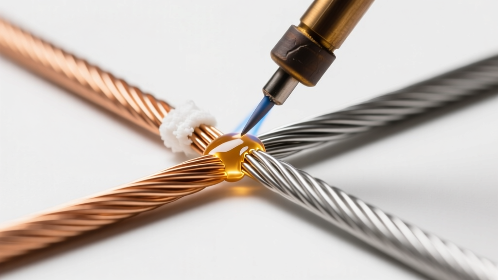
- The Cross: Cross the two wires in an 'X' shape, intersecting about one-third of the way down the stripped length.
- The Wrap: Wrap each wire end tightly around the opposing wire's base strand 4 to 5 times. Use lineman's pliers to pull the final wrap tight, ensuring no sharp protruding ends (which will pierce heat shrink later).
- Flux Application: Even if using flux-core solder, apply a small dab of external tacky flux (e.g., Amtech NC-559) to the splice. This guarantees oxide displacement across the dense wire matrix.
- Heat & Feed: Apply a tinned Hoof or Chisel tip to the bottom of the splice. Feed the solder wire (0.031" / 0.8mm diameter) to the top of the splice. Capillary action will draw the molten solder down through the entire joint. Stop feeding the moment a smooth, concave fillet forms around the wire wraps.
- Cooling: Remove the iron and hold the wires perfectly still for 4-6 seconds. Blowing on the joint or moving it while the eutectic alloy transitions from liquid to solid will cause a disturbed joint (characterized by a dull, grainy finish and micro-fractures).
Critical Warning: Never use the 'blob' method where you melt solder onto the iron tip and attempt to wipe it onto the wire. The flux will burn off before the wire reaches thermal equilibrium, resulting in a superficial cold joint that will snap under minor vibration.
Advanced Pairings: Heat Shrink Solder Sleeves
For environments where traditional splicing is too slow or where waterproofing is mandatory (e.g., marine electronics, automotive engine bays), pairing a heat gun with solder sleeves (like those from Weicon or 3M) is the optimal technique. These sleeves contain a pre-formed ring of flux-core solder flanked by polyolefin heat shrink and inner rings of hot-melt adhesive.
Execution Protocol for Solder Sleeves
- Strip Length: Match the strip length exactly to the metal ring inside the sleeve (usually 10mm - 15mm).
- Insertion: Interleave the stranded wires inside the sleeve so the bare copper sits directly beneath the solder ring.
- Thermal Profile: Use a hot air station set to 250°C with a high airflow nozzle. Apply heat evenly to the outer shrink first to secure the wire position, then focus intense heat directly on the solder ring until it flashes from solid to a bright liquid pool, then back to a dull solid.
- Sealing: The inner adhesive rings will melt and extrude slightly from the ends, indicating a complete hermetic environmental seal.
Troubleshooting Edge Cases & Failure Modes
Even with perfect tool pairing, environmental and material variables can introduce defects. Here is how to diagnose and correct the most common wire soldering failures.
1. Solder Wicking Under Insulation
The Failure: Capillary action pulls molten solder up the strands and beneath the PVC or silicone insulation. This creates a rigid, brittle section of wire right at the flex point, leading to fatigue fractures.
The Fix: Reduce your strip length. If soldering 18 AWG, strip no more than 6mm for a standard cup terminal or splice. Additionally, lower your iron temperature by 15°C to increase the time-to-melt, reducing the thermal window for wicking to occur.
2. Insulation Melt-Back
The Failure: The heat shrink or PVC jacket shrinks and melts away from the joint, exposing bare copper and risking short circuits.
The Fix: You are using an underpowered iron. An iron struggling to reach thermal equilibrium on a 12 AWG wire will require 15+ seconds of dwell time, transferring massive conductive heat down the wire to the jacket. Switch to a higher wattage station with a broader tip to achieve the joint in under 3 seconds.
3. The 'Grape' Joint (Non-Wetting)
The Failure: The solder balls up and sits on top of the wire like a grape, failing to flow into the strands. This is caused by severe oxidation on the wire or a depleted flux core.
The Fix: Mechanically clean the wire with a fiberglass scratch pen or fine-grit emery cloth before tinning. Apply a generous amount of external rosin flux and re-apply heat. If the solder is old (manufactured >3 years ago), the internal flux core may have dried out; discard and use fresh Kester 44 or equivalent.
Final Thoughts on Technique Mastery
Soldering wire connections is an exercise in thermal management. By respecting the physics of copper heat dissipation, matching your station's wattage and tip geometry to the specific AWG, and utilizing the correct splice mechanics, you transform a fragile DIY repair into an aerospace-grade interconnect. Invest in quality eutectic alloys, maintain your tips with brass wool rather than wet sponges, and let the flux do the heavy lifting.