
Why Beginners Struggle with Soldering Wire to Circuit Board Pads
When you are first learning the art of soldering wire to circuit board assemblies, the most common point of failure isn't a lack of steady hands—it is a fundamental misunderstanding of thermal mass and metallurgy. Many novices treat a soldering iron like a hot glue gun, melting solder onto the tip and attempting to "paint" it onto the wire and pad. This approach guarantees a cold joint, poor electrical conductivity, and eventual mechanical failure.
This comprehensive beginner walkthrough will reframe your approach. We will cover the exact tools, metallurgical principles, and step-by-step execution protocols required to create flawless, IPC-compliant joints every time. By the end of this guide, you will understand how to manipulate heat transfer to achieve perfect wetting on any printed circuit board (PCB).
The Toolkit: Stop Using Cheap Irons and Conical Tips
Before striking an arc, you must audit your workbench. The right equipment removes 90% of the friction from the learning curve.
The Soldering Station
Forget the $15 plug-in irons with no temperature control. You need a station with a fast-recovering ceramic heating element. The Hakko FX-601 (approximately $65) is a phenomenal mid-tier choice, offering rapid thermal recovery. If you are on a strict budget, the Pine64 Pinecil V2 ($25) is a 2026 community favorite; powered by a USB-C PD laptop charger, it reaches 350°C in under 15 seconds and offers incredible tip compatibility.
The Myth of the Conical Tip
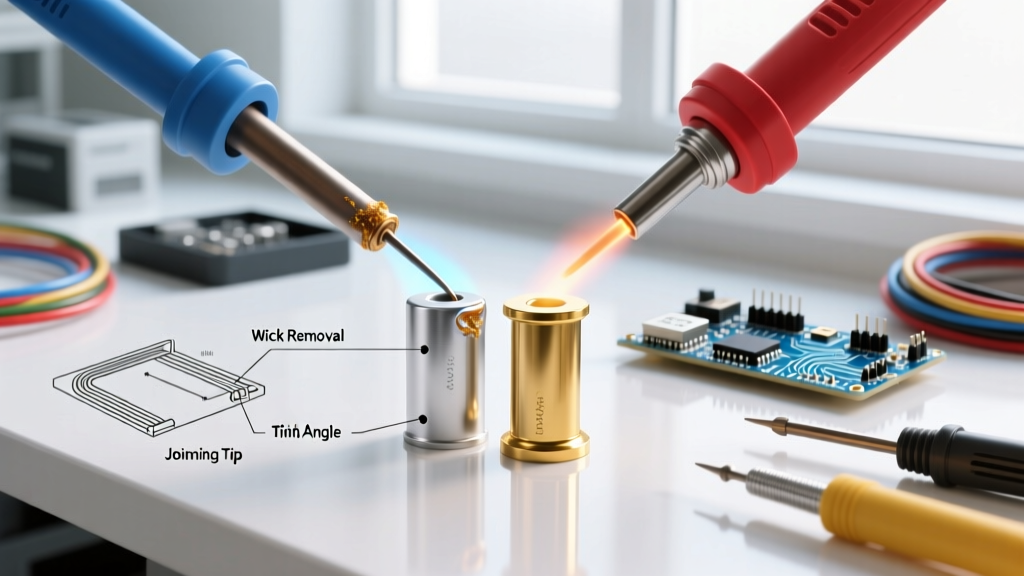
Beginners often default to the conical (pencil) tip that comes pre-installed on most budget irons. This is a critical mistake. A conical tip has minimal surface area at the very point, meaning thermal transfer to the copper pad is severely bottlenecked. When soldering wire to circuit board pads, you need rapid thermal equilibrium. A 2.4mm or 3.2mm chisel tip provides a flat plane that maximizes contact area, allowing heat to flow instantly into the joint. According to Hakko's official tip selection guide, matching the tip geometry to the thermal mass of the joint is the single most important factor in preventing cold joints and pad delamination.
Wire and Solder Selection
For general wire-to-board connections, 63/37 (Tin/Lead) solder is the undisputed champion for beginners. Why? Because it is a eutectic alloy. Unlike 60/40 solder, which has a "plastic" phase between its solidus and liquidus temperatures, 63/37 transitions instantly from solid to liquid at exactly 183°C (361°F). This eliminates the risk of "disturbed joints"—a grainy, fractured connection caused by microscopic vibrations while the solder is cooling. Kester 245 63/37 with a 0.031-inch (0.8mm) diameter and a 2% no-clean flux core remains the industry benchmark, typically retailing around $35 to $45 per pound.
For the wire, use 22 AWG or 24 AWG stranded silicone wire. Silicone insulation won't melt and shrink back when the iron gets close to the jacket, unlike PVC wire.
Preparation Protocol: The Non-Negotiable Tinning Step
Never attempt to join bare, untinned copper wire to a PCB pad. The copper oxidizes instantly when heated, creating an invisible barrier that solder will not adhere to.
- Strip the Wire: Remove exactly 3/16" to 1/4" of insulation. Do not nick the copper strands, as this creates a stress fracture point.
- Twist and Flux: Give the exposed strands a gentle twist to keep them unified. Dip the bare copper into a pot of MG Chemicals 8341 No-Clean Paste Flux ($12).
- Tin the Wire: Apply your chisel tip to the wire and feed the solder directly into the strands. The flux will boil and the solder will wick up into the wire via capillary action in about 1.5 seconds. Stop feeding solder the moment it reaches the insulation jacket.
Step-by-Step Execution: Soldering the Joint
With your wire pre-tinned and your iron stabilized at 340°C (644°F), you are ready to make the connection. We will follow the strict thermal transfer rules outlined in Adafruit's Guide to Excellent Soldering.
Step 1: Clean and Flux the Pad
Wipe the PCB pad with 99% Isopropyl Alcohol (IPA) to remove manufacturing oils. Apply a tiny dab of extra paste flux directly to the copper pad. Flux is the chemical agent that removes oxidation; without it, surface tension will prevent the solder from wetting the pad.
Step 2: The "Heat the Joint" Rule
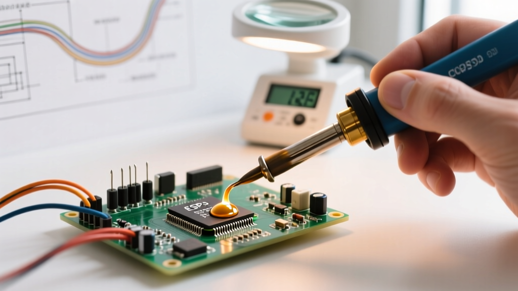
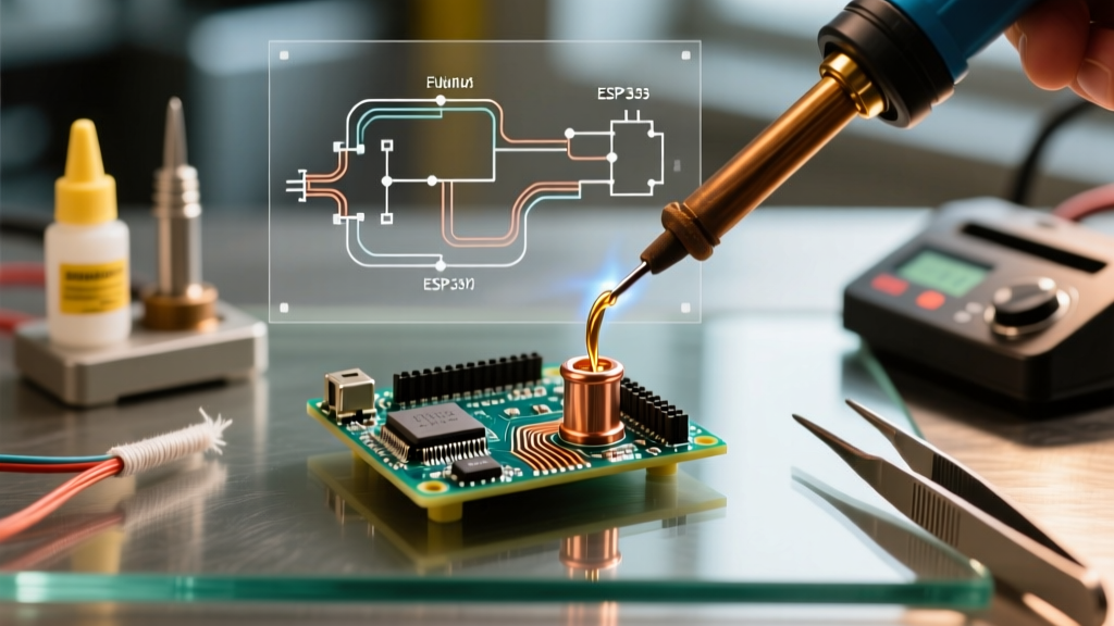
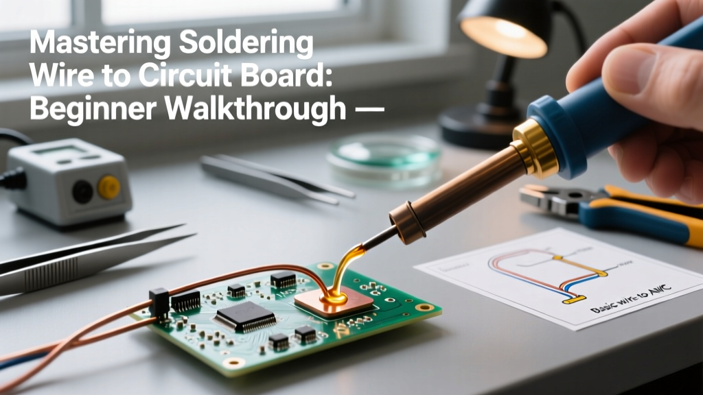
Place the flat side of your chisel tip so that it simultaneously touches the PCB pad and the side of your pre-tinned wire. Do not touch the solder to the iron yet. Hold the iron in place for 1 to 1.5 seconds to allow the copper pad to reach soldering temperature.
Step 3: Feed the Solder
Touch your solder wire to the opposite side of the joint, directly where the wire meets the pad. If the pad is hot enough, the solder will instantly melt and wick smoothly into the joint, forming a shiny, concave fillet. Feed only enough solder to cover the connection—usually about 1/8" of solder wire.
Step 4: The Retreat
Remove the solder wire first, then smoothly pull the iron away at a 45-degree angle. The entire heating process should take no more than 2.5 seconds. The joint will solidify in roughly 1 second.
Pro-Tip: A perfect joint should look like a miniature volcano or a "Hershey's Kiss." According to IPC-A-610 standards, the solder must exhibit excellent wetting, forming a concave fillet with a contact angle of less than 90 degrees where it meets the pad.
Troubleshooting Matrix: Diagnosing Bad Joints
Even with perfect technique, environmental factors and varying PCB thermal masses can cause defects. Use this matrix to diagnose and fix your errors.
| Defect | Visual Symptom | Root Cause | Corrective Action |
|---|---|---|---|
| Cold Joint | Dull, gray, grainy or lumpy texture | Insufficient heat transfer to the pad, or the wire moved before the solder fully crystallized. | Apply fresh flux. Reheat the joint with the iron until the solder flows completely smooth, then hold perfectly still while removing the iron. |
| Lifted Pad | Copper trace peeling off the green FR4 substrate | Dwell time exceeded 3-4 seconds, melting the epoxy bonding the copper to the board. | Stop immediately. Use a wider chisel tip to transfer heat faster next time. If the pad is lifted, you must scrape the trace back and run a jumper wire. |
| Solder Balling | Solder rolls off the pad into tiny spheres | Heavy oxidation on the PCB pad or a severely oxidized iron tip. | Clean your tip with brass wool (never use a wet sponge, it causes thermal shock). Scrub the pad with IPA, apply aggressive flux, and retry. |
| Icicle / Spike | Sharp, pointed protrusion extending from the joint | Too much solder applied, or pulling the iron away too slowly, causing the flux to burn off before the solder retracts. | Use copper desoldering braid (wick) with flux to absorb the excess solder, then reflow the joint cleanly. |
Edge Case: Battling Ground Planes and Thermal Vias
If you are soldering a wire to a pad connected to a large internal ground plane, you will experience "heat sinking." The massive copper area inside the board will rapidly pull heat away from your iron, making it seem impossible to melt the solder. Beginners often respond by cranking their iron up to 400°C+, which destroys the tip and burns the flux.
The Expert Solution: Do not increase the temperature; increase the thermal mass of your tip. Swap your 2.4mm chisel for a 4.0mm or 5.0mm bevel/chisel tip. The larger tip holds more thermal energy and can overpower the ground plane's heat-sinking effect without requiring dangerous temperature spikes. Alternatively, use a PCB pre-heater to bring the entire board to 100°C before applying the iron.
Final Thoughts on Workmanship
Mastering the process of soldering wire to circuit board pads is entirely about respecting the chemistry of flux and the physics of thermal transfer. By utilizing a eutectic 63/37 alloy, leveraging a flat chisel tip for maximum surface contact, and strictly adhering to the "heat the joint, not the solder" rule, you will produce joints that are both mechanically robust and electrically flawless. Keep your tip tinned, your flux abundant, and your dwell times under three seconds, and your workbench results will rival professional manufacturing standards.