
The Metallurgical Barrier: Why Aluminum and Copper Resist Bonding
Soldering aluminum to copper is widely considered one of the most frustrating tasks in electronics and electrical DIY. The difficulty does not stem from the copper, which solders easily, but from the aluminum. The moment bare aluminum is exposed to atmospheric oxygen, it instantly forms a microscopic, incredibly tough layer of aluminum oxide (Al2O3). This oxide layer melts at roughly 2,070°C (3,758°F)—far beyond the melting point of any standard soft solder or the thermal limits of a typical soldering iron.
Standard rosin-based fluxes (R, RMA, or RA) are chemically incapable of dissolving this aluminum oxide layer. Furthermore, the vast difference in thermal conductivity between the two metals means heat dissipates rapidly into the aluminum substrate, often resulting in cold, brittle joints. To successfully bridge these two dissimilar metals, you must abandon standard electronics soldering protocols and adopt a specialized metallurgical approach utilizing aggressive chemical fluxes and specific high-tin alloy fillers.
2026 Tooling and Consumables Matrix
Before striking an arc or heating an iron, you must procure the correct chemistry. Using standard 60/40 Sn/Pb or SAC305 wire with rosin core will result in immediate failure. Below is the required bill of materials for a reliable aluminum-to-copper transition joint.
| Category | Specific Product / Specification | Estimated Cost (2026) | Purpose |
|---|---|---|---|
| Flux | Superior Flux #4000 or La-Co 10050 (Zinc Chloride base) | $14 - $18 / 2oz | Dissolves Al2O3 oxide layer via aggressive chloride reaction. |
| Filler Alloy | Harris 80219 Al-Solder (97% Sn, 3% Ag) or Castolin 192 FW | $28 - $42 / oz | Wets aluminum and provides a transition layer for copper bonding. |
| Soldering Station | Weller WE1010NA or Hakko FX-888D (70W+ minimum) | $110 - $140 | Provides necessary thermal recovery for high-mass aluminum heat sinks. |
| Tip Geometry | Hakko T18-D24 or Weller ETA (Heavy Chisel, 2.4mm - 4mm) | $12 - $15 | Maximizes surface area contact for rapid thermal transfer. |
| Abrasion Tool | Stainless steel wire brush (dedicated, brass will contaminate) | $6 - $9 | Mechanical disruption of the oxide layer beneath the flux pool. |
The Galvanic Corrosion Trap
Critical Engineering Warning: Aluminum and copper sit on opposite ends of the galvanic series. When moisture and an electrolyte (even ambient humidity) are present, the aluminum will act as an anode and corrode rapidly to protect the cathodic copper. According to the American Galvanizers Association, this bimetallic coupling can destroy an unsealed joint in a matter of months in outdoor or high-humidity environments. Soldering itself does not stop galvanic corrosion; post-solder environmental sealing is mandatory for long-term reliability.
Step-by-Step Execution Protocol
This procedure assumes you are joining a solid or stranded copper wire to an aluminum terminal, tab, or wire. Ensure your workspace is well-ventilated; zinc chloride flux produces harsh, corrosive fumes when heated.
Step 1: Mechanical Prep and the 'Wet Scratch' Method
Do not simply sand the aluminum and then apply flux; the oxide will reform before the iron touches the metal. Instead, use the 'wet scratch' technique. Apply a generous pool of your zinc chloride flux (or a light layer of mineral oil if using a separate flux paste later) directly onto the aluminum surface. While the aluminum is submerged under this liquid barrier, use your stainless steel brush to aggressively scrub the joint area. The liquid prevents oxygen from reaching the freshly exposed raw aluminum, keeping it chemically active and ready to accept the solder.
Step 2: Thermal Management and Pre-Tinning the Aluminum
Set your soldering station to 380°C (715°F). Aluminum acts as a massive heat sink. If you are soldering a thick aluminum gauge, you may need to pre-heat the surrounding area with a hot air gun set to 150°C to reduce the thermal shock and delta-T.
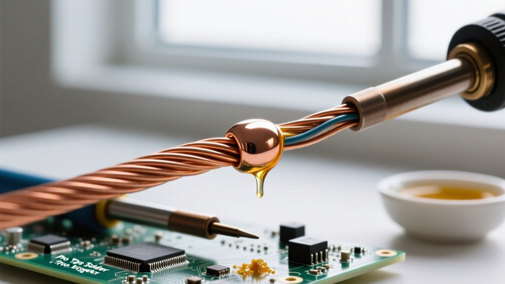
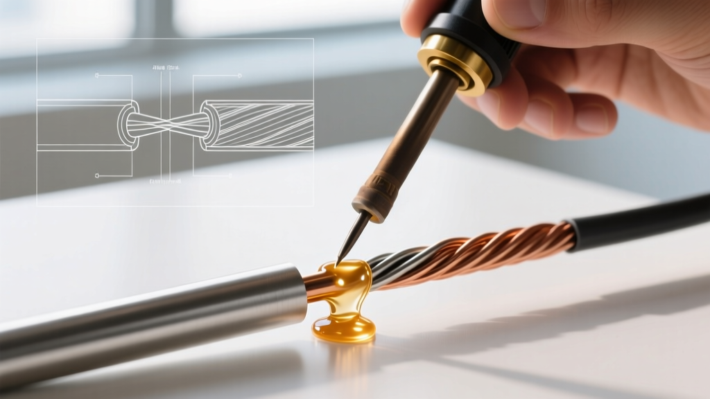
Apply the heavy chisel tip of your iron to the fluxed, scratched aluminum. Introduce the specialty aluminum solder (e.g., Harris Al-Solder) to the workpiece, not the iron tip. You are looking for a specific visual cue: the flux will boil, turn amber, and the silver-tin alloy will suddenly 'flash' and wet the surface, looking like a mirrored puddle. If the solder balls up and rolls off, the oxide layer was not fully breached. Re-brush under the flux and try again.
Step 3: Pre-Tinning the Copper
While the aluminum cools, prepare the copper. Strip the copper wire, apply a standard mildly activated rosin flux (do not use the zinc chloride flux on copper unless necessary, as it is highly corrosive and difficult to clean), and tin it with your specialty aluminum-compatible solder or a standard high-tin lead-free alloy. The goal is to create a uniform, shiny coating of solder on the copper that matches the metallurgical profile of the solder already on the aluminum.
Step 4: The Final Sweat Joint
Place the pre-tinned copper wire directly against the pre-tinned aluminum pad or wire. Apply the iron to the junction. Because both surfaces are already tinned with compatible alloys, the heat will quickly reflow the filler metals together. Hold the joint perfectly still for 5 to 8 seconds after removing the iron to allow the crystalline structure to solidify. Any movement during this cooling phase will result in a disturbed, grainy, and mechanically weak joint.
Failure Mode Analysis & Troubleshooting
Even with the correct materials, aluminum soldering presents unique failure modes. Refer to this diagnostic matrix if your joint fails visual or mechanical inspection.
| Visual Symptom | Root Cause | Corrective Action |
|---|---|---|
| Solder forms perfect beads but refuses to stick (wetting failure). | Incomplete oxide removal; flux was applied after scratching, allowing instant re-oxidation. | Re-abrade the aluminum strictly underneath a pool of flux or oil. |
| Joint looks dull, gray, and grainy. | Disturbed joint; movement occurred during the plastic-to-solid phase transition. | Reheat fully to liquid state, use a mechanical clamp or jig to hold still. |
| Copper wire pulls out of the solder blob with zero resistance. | Cold joint on the copper side; iron temperature too low or tip too small for thermal mass. | Upgrade to a heavier chisel tip; increase station temp to 400°C; pre-heat copper. |
| White, powdery crust forms on the joint hours after soldering. | Zinc chloride flux residue reacting with ambient moisture (highly acidic). | Neutralize immediately with a baking soda/water solution, then scrub with isopropyl alcohol. |
Post-Solder Neutralization and Environmental Sealing
Because you used a highly active, corrosive zinc chloride flux to penetrate the aluminum oxide, leaving the residue on the joint will guarantee long-term failure. The flux will continue to eat through the metal and create conductive dendrites. Immediately after the joint has cooled, wash the area with a mild baking soda and water solution to neutralize the acid, followed by a rigorous scrub with 99% isopropyl alcohol.
Once the joint is chemically clean and dry, you must address the galvanic corrosion risk mentioned earlier. Adhering to high-reliability standards similar to those outlined in NASA-STD-8739.3 for soldered interconnections, the joint must be hermetically sealed. Apply a generous coating of marine-grade heat shrink tubing lined with polyamide adhesive, or encapsulate the joint in a two-part epoxy or RTV silicone. This physical barrier starves the galvanic cell of the electrolyte (moisture) required for corrosion to occur, ensuring your aluminum-to-copper transition lasts for decades.
Summary of Best Practices
Soldering aluminum to copper is entirely feasible for the DIY electronics enthusiast or field technician, provided you respect the metallurgy. By utilizing the wet-scratch abrasion method, deploying aggressive zinc chloride fluxes, selecting high-tin silver-bearing filler metals, and rigorously sealing the final joint against galvanic action, you can create transition joints that rival mechanical crimps in both electrical conductivity and tensile strength. For further reading on baseline soldering acceptability criteria, consult the IPC J-STD-001 standard documentation to ensure your general workmanship remains within industry tolerances.