
The Thermal Divide: Defining the 840°F (450°C) Threshold
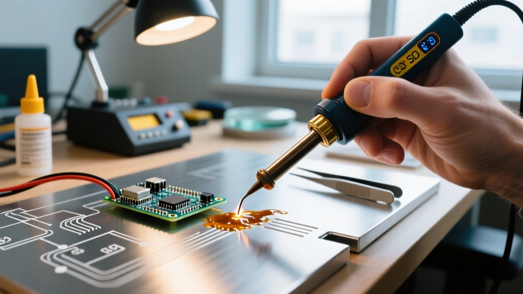
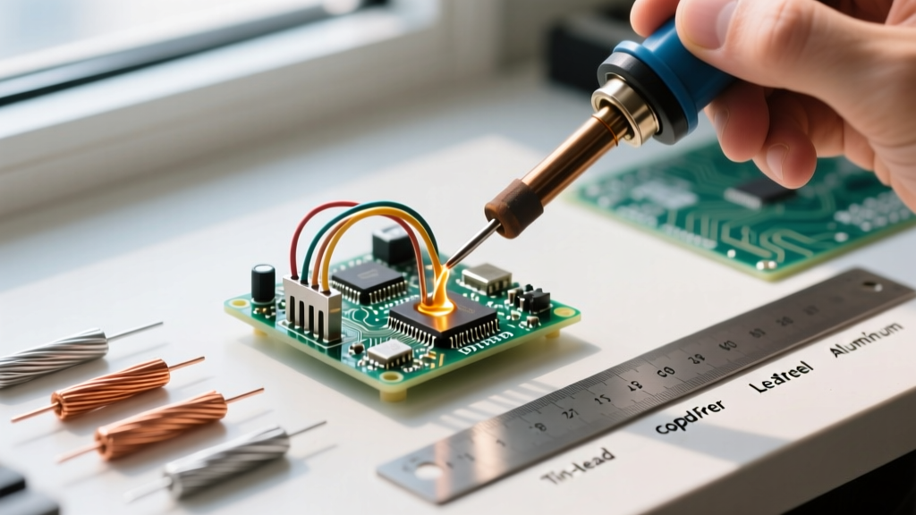
When tackling advanced DIY electronics, HVAC repair, or structural metalwork, understanding what's the difference between brazing and soldering is critical to preventing catastrophic joint failures. While both processes join metals using a filler material that melts at a lower temperature than the base metals, the metallurgical mechanics, thermal thresholds, and structural outcomes are vastly different.
According to the American Welding Society (AWS) and standard industry definitions, the dividing line is strictly thermal. If the filler metal melts below 840°F (450°C), the process is soldering. If it melts above 840°F (450°C) but below the melting point of the base metals, it is brazing. This single temperature threshold dictates everything from the flux chemistry required to the shear strength of the final joint.
Advanced Insight: The 840°F threshold isn't arbitrary. It represents the approximate temperature at which filler metals transition from relying primarily on surface-level intermetallic bonding (soldering) to achieving deep solid-state diffusion and capillary penetration (brazing).Metallurgical Mechanics: Intermetallic Compounds vs. Solid-State Diffusion
To truly master these techniques, you must look at the microscopic level. The fundamental difference lies in how the filler metal interacts with the base metal's grain structure.
Soldering: The Intermetallic Layer (IMC)
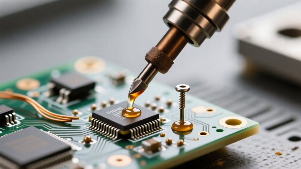
In soldering, the filler metal (like SAC305 or Sn63/Pb37) does not deeply diffuse into the base metal. Instead, it forms a thin Intermetallic Compound (IMC) at the boundary. For copper-to-tin soldering, this creates a Cu6Sn5 layer. This layer is electrically conductive and provides adequate mechanical holding power for PCB components, but it is inherently brittle. If subjected to high shear stress or thermal cycling, the IMC can micro-fracture, leading to the dreaded 'cold joint' or pad lift.
Brazing: Solid-State Diffusion
Brazing operates at temperatures where atomic mobility is significantly higher. The filler metal (often silver, copper, or brass-based) actually diffuses into the microscopic grain boundaries of the base metal. As detailed in Lucas Milhaupt's brazing fundamentals, this creates a joint that is often stronger than the base metals themselves. The failure point in a properly brazed joint will typically be the base metal tearing, not the filler metal shearing.
Joint Clearance and Capillary Flow Dynamics
A common mistake advanced DIYers make is applying soldering clearances to brazed joints, or vice versa. Capillary action draws the molten filler into the joint, but the optimal gap width varies drastically between the two processes.
- Soldering Clearances: Optimal radial clearance is extremely tight, typically 0.001 to 0.003 inches. If the gap is wider, the solder will not bridge effectively, leading to voids and weak mechanical bonds.
- Brazing Clearances: Because brazing alloys have higher viscosity and rely on deeper diffusion, the optimal clearance is wider, generally 0.002 to 0.005 inches at the brazing temperature (accounting for thermal expansion of the base metals).
The Ultimate Comparison Matrix
| Characteristic | Soldering | Brazing |
|---|---|---|
| Temperature Threshold | Below 840°F (450°C) | Above 840°F (450°C) |
| Typical Heat Source | Iron (Weller, Hakko), Hot Air, Propane | Oxy-Acetylene, MAP-Pro, Induction |
| Joint Shear Strength | 3,000 - 8,000 psi | 40,000 - 70,000+ psi |
| Primary Flux Type | Rosin (RMA), Mild Organic Acids | Fluoride/Borate compounds |
| Base Metal Alteration | None (Metallurgical properties intact) | Possible annealing or grain growth |
| Primary Applications | PCBs, Electronics, Light Copper Plumbing | HVAC, Structural Steel, Aerospace, Tools |
Flux Chemistry: Rosin vs. Refractory Oxide Dissolvers
Flux is not interchangeable between these two processes. Using soldering flux for brazing will result in immediate failure, as the flux will vaporize and burn into a carbon crust long before the brazing alloy reaches its liquidus point.
Soldering Fluxes: In electronics, we rely on Rosin Mildly Activated (RMA) or no-clean synthetic resins. These are designed to remove light surface oxidation at 220°C without damaging sensitive silicon components. For copper plumbing, mild organic acid pastes (like Oatey No. 95) are used.
Brazing Fluxes: Brazing requires aggressive chemical reducers capable of dissolving refractory oxides at 1,200°F+. The industry standard is Harris Black Flux, which contains potassium fluoroborate and potassium fluoride. As noted by Machine Design's joining engineering guides, these fluoride compounds actively etch the base metal at high temperatures, allowing the silver or copper filler to wet the surface. Note: When brazing copper-to-copper with a phosphorus-bearing alloy (like Sil-Fos), the phosphorus acts as a self-fluxing agent, eliminating the need for external flux.
Filler Metals and 2026 Economics
Understanding the cost-to-performance ratio of filler metals is vital for project planning. Here is a breakdown of standard advanced alloys and their approximate market pricing as of 2026:
- SAC305 (Sn96.5/Ag3.0/Cu0.5): The undisputed king of lead-free electronics soldering. Melts at 217°C-220°C. Excellent wetting and reliable IMC formation. Cost: ~$45 - $65 per pound.
- BCuP-5 (Sil-Fos 5 / 5% Silver): A staple in HVAC and refrigeration brazing. The phosphorus provides self-fluxing on copper, while the 5% silver increases ductility and vibration resistance. Melts at 1,195°F - 1,475°F. Cost: ~$160 - $220 per pound (highly dependent on silver spot markets).
- BAg-24 (50% Silver / Cad-Free): Used for brazing steel, stainless, and dissimilar metals where self-fluxing phosphorus alloys won't work. Requires heavy fluoride flux. Cost: ~$400+ per pound.
Advanced Edge Cases and Failure Modes
Even experienced fabricators encounter edge cases when pushing the limits of these joining methods. Here is how to troubleshoot advanced failure modes:
The HVAC Cupric Oxide Scale Problem
When brazing copper pipes for refrigeration, the high heat introduces oxygen into the pipe's interior, creating cupric oxide scale (black flaking inside the pipe). This scale breaks off and destroys compressor valves. The Fix: You must purge the lines with dry nitrogen at 2 to 3 SCFH (Standard Cubic Feet per Hour) during the entire brazing process. This displaces the oxygen and keeps the interior pristine.
PCB Pad Lifting from Thermal Shock
When soldering heavy ground planes on multi-layer PCBs, the massive heat sink effect tempts users to crank their iron to 450°C. This destroys the FR4 epoxy resin and delaminates the copper pad. The Fix: Adhere to IPC J-STD-001 standards by using a high-thermal-mass chisel tip at 350°C, utilizing a pre-heater to bring the board ambient up to 120°C, and relying on capillary flow rather than brute-force heat.
Base Metal Annealing in High-Carbon Steel
Brazing high-carbon steel (like lawnmower blades or springs) with brass can inadvertently anneal the steel if the heat is held too long, ruining its temper and hardness. To prevent this, use localized induction heating or a highly focused oxy-acetylene flame to achieve rapid thermal cycling, minimizing the time the base metal spends in the critical annealing temperature zone.
Summary: Choosing the Right Process
Ultimately, what's the difference between brazing and soldering comes down to the mechanical demands of your project. If you are routing micro-amps on a PCB or joining low-pressure domestic water lines, the low-thermal-stress, IMC-reliant process of soldering is your only viable option. However, if your DIY project involves structural loads, high-pressure refrigerants, or vibrational stress, you must cross the 840°F threshold and utilize the deep-diffusion, high-shear strength of brazing. Mastering both—and knowing exactly when to deploy each—is the hallmark of a true fabrication expert.