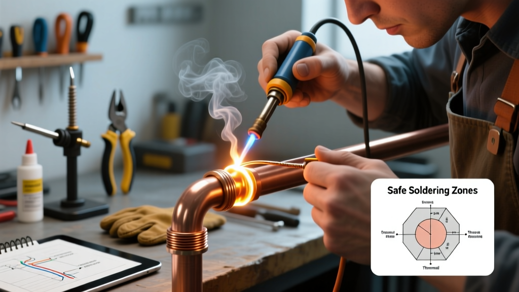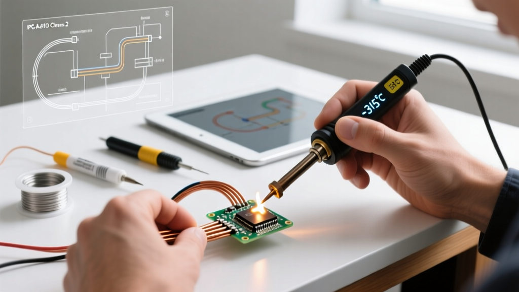

The Anatomy of a Professional Wire Solder Joint
Learning how to solder wire is often the first skill an electronics hobbyist acquires, yet it remains one of the most frequently botched procedures in field repairs and DIY builds. A professional solder joint is not merely a mechanical blob of metal holding two conductors together; it is a precise metallurgical bond. According to the IPC J-STD-001 standard for soldered electrical assemblies, a flawless wire connection requires proper wetting, where the molten solder dissolves a microscopic layer of the base metal to form an intermetallic compound (IMC). This IMC layer is what provides both electrical conductivity and mechanical tensile strength.
In 2026, with the proliferation of high-current DIY battery packs, automotive CAN-bus modifications, and audiophile equipment, the margin for error has shrunk. A high-resistance cold joint in a 12AWG drone power lead can cause a thermal runaway event. This guide bypasses amateur guesswork and details the exact professional workflows, temperatures, and material science required to solder wire like a certified aerospace technician.
Essential Gear: The 2026 Professional Workstation
You cannot achieve IPC Class 3 (High-Performance) reliability with a $20 plug-in iron. Thermal recovery and tip geometry are non-negotiable.
1. The Soldering Station
- Hakko FX-951 or FX-952: The industry standard for bench work. Priced around $275 in 2026, it utilizes T12 cartridge tips where the heating element and sensor are integrated, offering near-instant thermal recovery when hitting thick copper strands.
- Weller WE1010NA: An excellent mid-tier alternative ($125-$135) featuring a 70W heating element and digital temperature control, ideal for general 22AWG to 14AWG wire soldering.
2. Tip Geometry: The Conical Trap
Amateurs default to conical (pencil) tips for wire. This is a critical error. Conical tips have minimal surface area, resulting in poor heat transfer to the copper strands. Professionals use Chisel tips (e.g., Hakko T12-D24 or T12-D32). The flat blade maximizes contact area with the cylindrical wire, reducing dwell time and preventing insulation melt-back.
3. Solder Alloy Selection
For general wire soldering, eutectic Sn63/Pb37 (63% Tin, 37% Lead) remains the undisputed king of reliability. It melts at a precise 183°C (361°F) with no plastic (pasty) phase, eliminating disturbed-joint failures. Kester 44 (0.031-inch diameter, Rosin core) is the benchmark. If your project mandates RoHS compliance, you must use SAC305 (Sn96.5/Ag3.0/Cu0.5), which melts at 217°C-220°C and requires a more aggressive flux and higher iron temperatures.
Step-by-Step Professional Workflow
Follow this exact sequence to ensure capillary action pulls the solder deep into the wire strands.
Step 1: Precision Stripping and Preparation
Use a calibrated wire stripper (like the Knipex Super 4) to avoid nicking the copper strands. A nicked strand creates a stress riser that will snap under vibration. Rule of thumb for strip length: For 18AWG wire, strip exactly 0.375 inches (9.5mm). The wire should insert into the terminal or splice with no bare copper exposed outside the joint, and no insulation entering the solder cup.
Step 2: The Tinning Phase
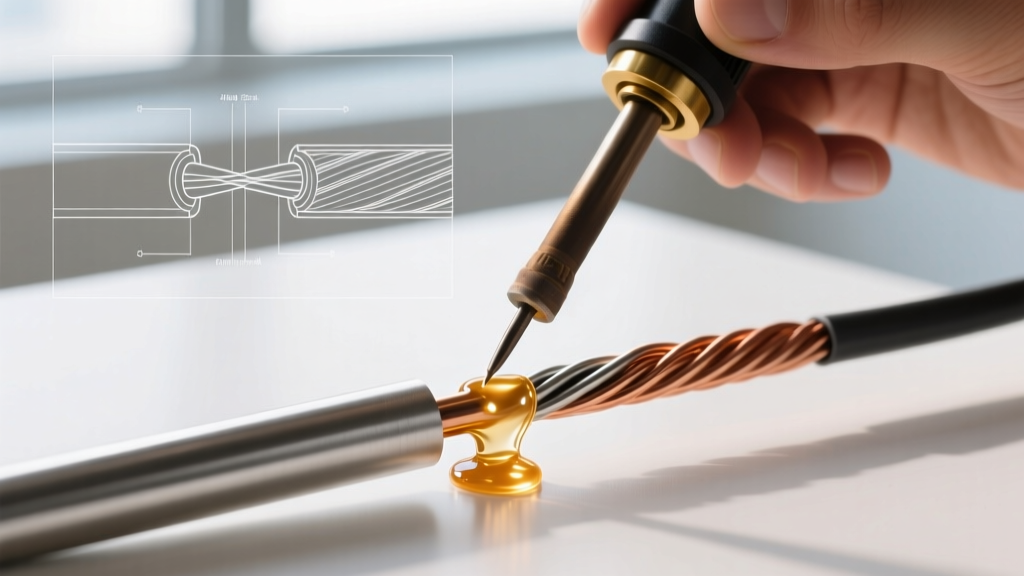
Never attempt to solder two bare wires together simultaneously. Tin each wire individually first. Apply a microscopic amount of fresh solder to the iron tip to create a thermal bridge. Press the chisel tip against the bare wire strands, wait 1 second for the copper to reach melting temperature, and feed the rosin-core solder directly into the wire strands—not the iron tip. The flux will boil, and capillary action will wick the solder to the base of the insulation.
Step 3: Mechanical Splicing (The IPC Way)
Once both wires are tinned, lay them parallel or use a very gentle twist. Do not use the tight 'Western Union' twist for stranded wire. While popular in amateur tutorials, tight twists trap unactivated acidic flux in the center of the splice, leading to long-term galvanic corrosion, and make desoldering for repairs virtually impossible.
Step 4: The Final Melt
Place the pre-tinned wires together. Apply the iron to the side of the joint. The existing solder will instantly reflow and fuse the two conductors into a single homogeneous mass. Total dwell time on the wire should not exceed 2.5 seconds.
Troubleshooting Matrix: Diagnosing Wire Soldering Failures
Even seasoned technicians encounter anomalies. Use this diagnostic matrix to identify and correct defects based on NASA Electronic Parts and Packaging (NEPP) workmanship criteria.
| Defect Type | Visual Indicator | Root Cause | Professional Fix |
|---|---|---|---|
| Cold Joint | Dull, gray, grainy, or lumpy surface | Insufficient heat transfer; iron temp too low or tip oxidized | Increase station temp by 20°C; re-tin tip; ensure chisel tip is flat against wire |
| Wicking | Solder creeps under the wire insulation | Dwell time too long; wire stripped too far | Limit contact to 2 seconds; reduce strip length by 1/16 inch |
| Disturbed Joint | Frosty, cracked, or ridged appearance | Wire moved while the SAC305 or Sn63 alloy was in its plastic cooling phase | Use a silicone mat or helping hands to immobilize wires for 4 seconds post-heat |
| Burnt Flux | Black, crusty residue; charred insulation | Iron temperature excessively high (over 400°C for leaded) | Drop temp to 320°C (608°F) for Sn63; apply external liquid flux (e.g., Amtech) instead of relying on core |
| Insufficient Wetting | Solder balls up and rolls off the copper | Oxidized wire (common in old marine/automotive harnesses) | Scrape strands with a fiberglass scratch pen before tinning; use high-activity RA flux |
Advanced Edge Cases: Soldering to Lugs and Solder Cups
When terminating a wire into a ring terminal lug or a DB9 solder cup, the thermal mass equation changes. The brass or copper lug acts as a massive heatsink.
- Pre-heat the Terminal: Place the iron tip on the metal lug first, not the wire.
- Feed Solder to the Cup: Touch the solder to the lug. When the lug reaches temperature, the solder will flow smoothly into the cup.
- Insert the Wire: While the solder in the cup is molten, slide the pre-tinned wire into the cup. Remove the iron and hold perfectly still.
Expert Insight: If you are using heat-shrink solder sleeves (like those from Raychem/Tyco), do not use a soldering iron. These sleeves require a calibrated heat gun set to roughly 200°C-250°C to activate the internal flux ring and melt the pre-form solder insert evenly without scorching the outer polyolefin insulation.
Final Inspection and Strain Relief
A solder joint should never bear mechanical load. Once the joint is verified visually—looking for a smooth, shiny, concave fillet that wets completely to the wire strands—you must apply strain relief. In 2026, adhesive-lined dual-wall heat shrink (such as 3M EPS-300) is the mandatory standard. The inner layer of hot-melt adhesive seals out moisture and locks the wire in place, while the outer layer provides electrical insulation and abrasion resistance. Never rely on electrical tape for professional wire splices; the adhesive degrades under thermal cycling and leaves a conductive, gummy residue that attracts dirt and compromises the harness over time.
Mastering how to solder wire is about respecting the metallurgy, controlling thermal mass, and adhering to established aerospace and commercial standards. By upgrading your tip geometry, respecting dwell times, and understanding the behavior of eutectic alloys, your electrical connections will achieve the reliability demanded by modern high-performance electronics.