
The Metallurgy of Failure: Why Your Soldering Iron and Solder Repel Each Other
There are few things more frustrating in electronics assembly than touching a perfectly clean component lead with your iron, only to watch the solder ball up and roll away. When your soldering iron and solder refuse to bond, you are witnessing a metallurgical failure at the microscopic level. Specifically, you are dealing with a failure in 'wetting'—the ability of molten solder to flow and adhere to a base metal via intermetallic compound (IMC) formation.
In 2026, with the widespread adoption of complex lead-free alloys and high-density PCBs, thermal management and surface chemistry are more critical than ever. Whether you are using a $28 Pine64 Pinecil V2 or a $150 Weller WE1010NA digital station, the physics of wetting remain identical. This guide dives deep into the exact failure modes of solder joints and provides actionable, laboratory-grade troubleshooting protocols to restore your equipment.
Diagnosing 'Black Tip' Syndrome (Oxidation)
The most common reason a soldering iron and solder fail to interact is tip oxidation. The iron plating on modern soldering tips is a microscopically thin layer of chromium or iron designed to protect the underlying copper core from dissolving into the molten tin. When exposed to high temperatures and atmospheric oxygen, this plating oxidizes, forming a barrier that solder simply cannot wet.
Expert Warning: Never file or sand a modern soldering tip. Unlike the solid copper tips of the 1980s, modern tips have a plating thickness of only 0.1mm to 0.2mm. Abrading the tip exposes the copper core, which will rapidly dissolve into the solder alloy, destroying the tip in minutes.
According to Hakko's official maintenance guidelines, oxidation accelerates exponentially when tip temperatures exceed 380°C (716°F) or when the iron is left idle without a protective layer of fresh solder. If your tip appears black, blue, or crusty, and solder beads off it like water on a hot skillet, oxidation is your culprit.
The 4-Step Tip Recovery Protocol
If your tip has oxidized, do not throw it away immediately. Follow this chemical and mechanical recovery sequence:
- Lower the Temperature: Drop your station to 250°C (482°F). High heat will instantly vaporize the flux in your tip tinner before it can work.
- Apply Active Tip Tinner: Use a specialized abrasive-chemical paste like the Hakko 599B Tip Tinner or MG Chemicals 4901. These contain mild abrasives (like glass beads) suspended in a highly active rosin or organic acid flux.
- The 'Swirl and Wipe' Technique: Gently swirl the tip in the tinner for 3–5 seconds. The flux will chemically reduce the metal oxides, while the abrasives physically clear the debris.
- Immediately Re-tin: Wipe the tip on a brass wire sponge (never a wet cellulose sponge, which causes thermal shock and micro-cracking in the plating) and immediately apply a thick layer of fresh, flux-cored Sn63/Pb37 or SAC305 solder to seal the surface.
Thermal Mass Mismatches and Cold Joints
Sometimes the soldering iron and solder bond initially, but the resulting joint is dull, grainy, and mechanically weak. This is a 'cold joint,' often caused not by a lack of heat at the heater element, but by a failure to transfer thermal energy to the joint due to a thermal mass mismatch.
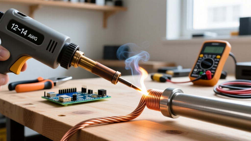
A 70W station like the Hakko FX-888D ($110–$120) has excellent thermal recovery, but if you are using a micro-pencil tip (e.g., T18-I) to solder a large ground plane or a 12AWG XT60 connector wire, the tip will instantly lose its heat to the massive copper sink. The solder will melt from the iron's residual heat, but the base metal will never reach the activation temperature required for the flux to clean the surface and the solder to form an IMC layer.
Soldering Iron and Solder Compatibility Matrix
Use the table below to match your tip geometry, iron wattage, and solder gauge to the specific thermal mass of your project.
| Application / Thermal Mass | Recommended Tip Geometry | Optimal Station Wattage | Solder Gauge & Alloy |
|---|---|---|---|
| 0402 / 0603 SMD Components | Micro-Pencil (0.4mm - 1.0mm) | 40W - 65W (Precise control) | 0.3mm Sn63/Pb37 or SAC305 |
| Through-Hole ICs & 22AWG Wire | Chisel (2.0mm - 3.2mm) | 60W - 75W | 0.5mm - 0.8mm Sn63/Pb37 |
| Heavy Ground Planes & 12AWG | Heavy Chisel or Bevel (5.0mm+) | 100W+ (e.g., Weller WXP120) | 1.0mm+ with external liquid flux |
For high-mass joints, always pre-heat the PCB using a bottom-side preheater (like the Quick 853A) set to 120°C. This reduces the delta-T (temperature difference) your iron must overcome, preventing cold joints and pad lift-off.
Flux Burn-Off and the 'Dry Joint' Phenomenon
Flux is the unsung hero of the soldering process. Its primary job is to dissolve metal oxides on the component lead and PCB pad, allowing the molten solder to wet the surface. However, flux has a specific activation temperature and a finite lifespan.
Most standard rosin-based (RMA) fluxes activate between 180°C and 220°C and burn off completely within 3 to 5 seconds at 350°C. If you apply your iron to the joint, wait too long for the massive component to heat up, and then feed the solder, the flux inside the solder wire will have already vaporized. Without active flux, the solder will form a dry, non-wetting blob. As detailed in Indium Corporation's technical resources on solder alloys, introducing external liquid or tacky flux (like Amtech NC-559-V2-TF) is mandatory when working with lead-free alloys or oxidized vintage boards where the dwell time exceeds 4 seconds.
Preventative Maintenance Schedule
To ensure your soldering iron and solder always interact predictably, implement this strict maintenance matrix in your workshop. Consistency is the hallmark of professional IPC-certified assembly.
| Frequency | Maintenance Action | Tools Required |
|---|---|---|
| Every Use | Always leave a large blob of solder on the tip before powering down. This sacrificial layer oxidizes instead of the tip plating. | Standard flux-cored solder |
| Daily | Clean tip using dry brass wire sponge. Avoid water sponges unless using distilled water, as tap water minerals cause pitting. | Hakko 599B or Edsyn BR10 |
| Weekly | Inspect tip for pitting or de-wetting under a 10x magnification loupe. Re-tin using active tip tinner if edges look dull. | MG Chemicals 4901 Tip Tinner |
| Monthly | Calibrate station temperature using a digital tip thermometer. Ensure the displayed temp matches the actual tip temp within ±5°C. | Hakko FG-100B Thermometer |
Frequently Asked Questions
Why does my solder melt on the iron but not stick to the wire?
This is a classic thermal transfer issue. The iron is hot enough to melt the alloy (e.g., 183°C for Sn63/Pb37), but the wire has not reached the temperature required to activate the flux and form an intermetallic bond. You must heat the wire with the iron for 1-2 seconds before feeding the solder into the joint, not onto the iron tip.
Is it safe to use liquid flux on all PCBs?
No. While No-Clean (NC) fluxes are generally safe to leave on boards, Water-Soluble (OA - Organic Acid) fluxes are highly corrosive. If you use water-soluble flux to rescue a difficult joint, you must clean the PCB with distilled water and an ESD-safe brush immediately after soldering, or the residue will eat through the copper traces within weeks. Always refer to Weller's soldering knowledge base for best practices on flux selection and tip pairing.
How long should a soldering iron tip last?
In a professional environment running 8 hours a day at 350°C, a high-quality tip (like Weller RT or Hakko T18 series) should last 3 to 6 months. In a hobbyist setting, if you practice proper tinning and avoid abrasive cleaning, a single tip can easily last 5 to 10 years.