
The Symbiosis of Heat and Chemistry
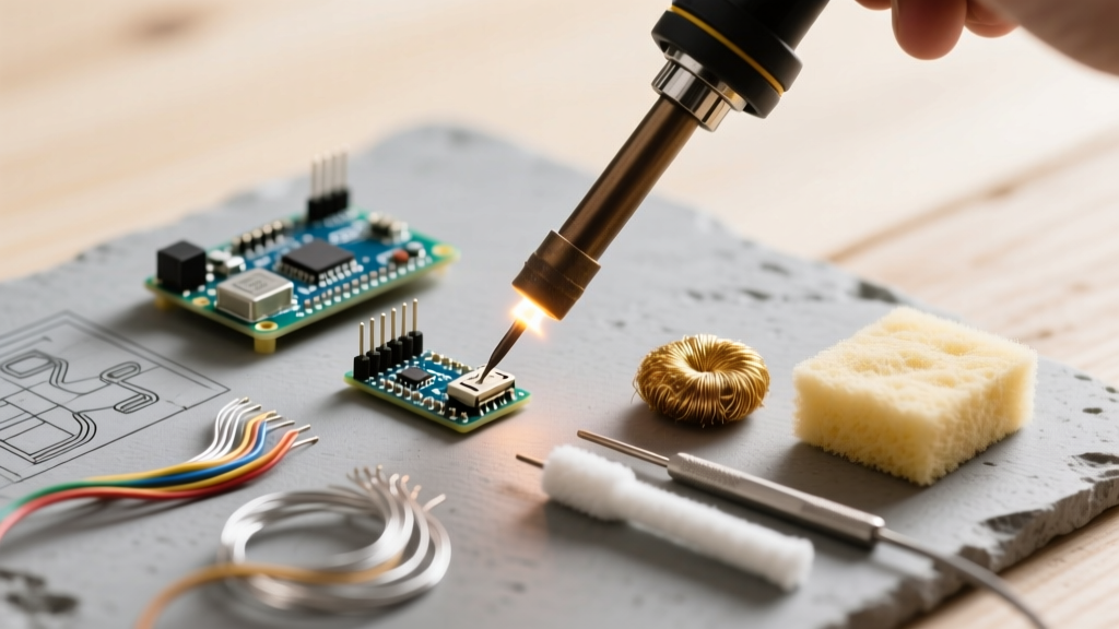
The relationship between a soldering iron and flux is frequently misunderstood by hobbyists as merely a hot tool meeting a sticky paste. In professional electronics manufacturing and advanced DIY prototyping, this pairing is recognized as a precisely orchestrated thermal-chemical reaction. The soldering iron provides the thermal energy required to melt the alloy, but it is the flux that dictates the metallurgical success of the joint by managing surface tension, oxide reduction, and heat transfer. As we move further into 2026, with the widespread adoption of complex lead-free alloys like SAC305 (Sn96.5/Ag3.0/Cu0.5) and miniaturized 0201 components, understanding the exact interplay between your iron's thermal recovery and your flux's activation curve is no longer optional—it is critical.
The Thermal-Chemical Handoff
A common beginner mistake is using the soldering iron to melt the solder wire directly, then transferring the molten blob to the joint. This bypasses the primary function of the iron, which is to elevate the temperature of the substrate (the PCB pad and component lead). The flux acts as the bridge in this thermal handoff.
When the iron tip touches the joint, the flux immediately begins to melt and flow. In its liquid state, flux dramatically increases the thermal coupling between the iron tip and the component lead. It displaces ambient air and microscopic contaminants, creating a high-efficiency thermal conduit. According to the NASA Workmanship Training Manual for Soldering, proper heat transfer requires the flux to activate before the solder alloy reaches its liquidus state, ensuring oxides are stripped away just milliseconds before the molten solder flows.
Activation Temperature Matrix
Not all fluxes activate at the same temperature. Pairing a high-activation flux with a low-wattage iron (like a basic 40W pencil) often results in the flux burning off before the joint reaches reflow temperature. Below is a functional matrix mapping flux types to optimal station settings.
| Flux Classification | Base Type | Activation Temp | Burn-off / Char Temp | Recommended Iron Tip Temp (SAC305) |
|---|---|---|---|---|
| ROL0 (No-Clean) | Rosin / Synthetic | 150°C - 170°C | ~320°C | 320°C - 340°C |
| ROM1 (Mildly Active) | Rosin + Halides | 140°C - 160°C | ~350°C | 330°C - 350°C |
| ORH1 (Water Soluble) | Organic Acid | 120°C - 140°C | ~280°C | 300°C - 320°C (Fast dwell) |
| REH0 (Synthetic Resin) | Synthetic | 160°C - 180°C | ~380°C | 340°C - 360°C |
IPC Standards and Flux Chemistry
To truly master the soldering iron and flux dynamic, one must look at the IPC-J-STD-004 standard, which categorizes fluxes by material type, activity level, and halide content. The standard uses a three-character code (e.g., ROL0). The first two letters denote the base material (RO for Rosin, OR for Organic, RE for Resin, IN for Inorganic). The third letter denotes activity level (L for Low, M for Moderate, H for High). The final number indicates halide presence (0 for none, 1 for present).
Expert Insight: When using an ORM1 (Organic, Moderate activity, Halides present) water-soluble flux for heavy ground-plane soldering, the halides aggressively strip copper oxides. However, if your soldering iron lacks the thermal mass to complete the joint within 2 to 3 seconds, the halides will begin attacking the iron plating of your tip, leading to catastrophic de-wetting.
Metallurgical Degradation: When Flux Attacks the Iron
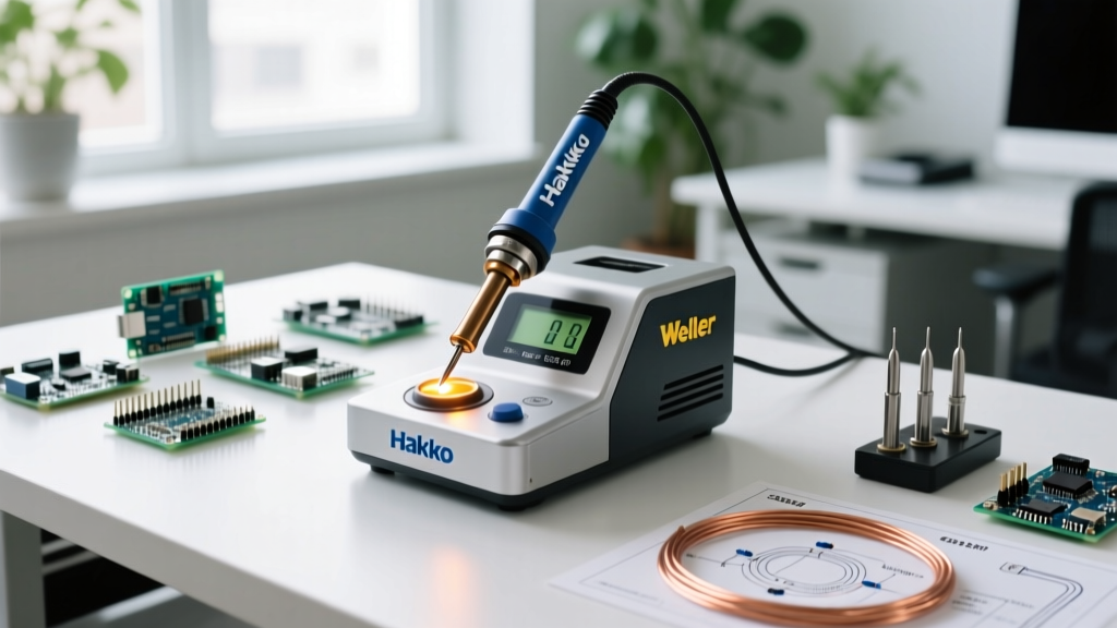
The tip of a modern soldering station (such as the Hakko FX-951 or JBC CD-2BQF) is not solid metal. It is a complex composite: a copper core for rapid heat transfer, plated with a 100 to 150-micron layer of iron to resist erosion, and finally flash-plated with chromium to prevent solder from creeping up the shaft. The working face is tinned with a thin layer of solder.
The chemical interaction between your chosen flux and this iron plating dictates the lifespan of your consumables.
- Rosin-Based (ROL0) Fluxes: Highly forgiving. The rosin encapsulates the tip, protecting the iron plating from atmospheric oxidation when the iron is idle in its holder.
- Water-Soluble (ORH0/1) Fluxes: Highly corrosive at high temperatures. If left on the tip during idle periods, the organic acids will pit the iron plating, exposing the copper core. Once the copper is exposed, it rapidly dissolves into the solder alloy, creating a hollowed-out tip that must be discarded.
- Inorganic Acid (IA) Fluxes: Often sold as 'plumber's paste' or 'acid flux'. Never use these on electronics PCBs or with standard iron-plated tips. They will destroy a $15 Hakko T18 tip in a matter of minutes.
Failure Modes: Diagnosing the Iron-Flux Mismatch
When the thermal output of the iron and the chemical properties of the flux are misaligned, specific failure modes manifest on the PCB. Recognizing these allows for immediate troubleshooting.
1. The 'Black Crust' De-wetting Phenomenon
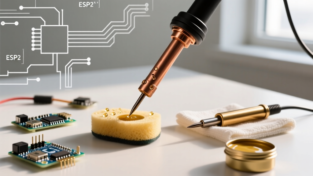
Symptom: Solder balls up and rolls off the tip; the tip appears charred black. Root Cause: The soldering iron temperature exceeds the flux's burn-off threshold. For standard ROL0 no-clean fluxes, sustained temperatures above 380°C cause the rosin to carbonize. This carbon layer acts as an insulator, preventing further heat transfer. Solution: Drop the station temperature to 320°C. Use a brass wire sponge (never a wet sponge, which causes thermal shock and micro-fractures in the iron plating) to mechanically remove the carbon, then immediately re-tin with fresh 63/37 Sn/Pb solder.
2. Premature Flux Burnout and Cold Joints
Symptom: The solder flows but forms a dull, grainy, disturbed joint with poor wetting angles. Root Cause: The thermal mass of the component (e.g., a large electrolytic capacitor or a multi-layer ground via) absorbs heat too quickly. The flux activates and burns off before the copper pad reaches the 217°C required to melt SAC305 solder. Without active flux, the molten solder hits an oxidized surface and fails to form an intermetallic compound (IMC) layer. Solution: Do not just increase the iron temperature, which will only burn the flux faster. Instead, increase the thermal transfer rate by switching to a larger tip geometry (e.g., moving from a 0.4mm conical to a 2.4mm chisel or a JBC C115-112 knife tip) to maximize surface contact area, and apply additional liquid flux directly to the joint before heating.
Step-by-Step Calibration for Optimal Wetting
To achieve perfect intermetallic bonding, follow this calibrated sequence designed for modern lead-free assembly:
- Prep the Substrate: Apply a small amount of tacky ROL1 flux to the target pads. This lowers the surface tension before heat is even applied.
- Set the Station: Calibrate your station (e.g., Weller WE1010NA) to 340°C. Allow the tip to soak at this temperature for 30 seconds to ensure the internal ceramic heating element has stabilized.
- Bridge the Gap: Apply the tinned tip simultaneously to the pad and the component lead. Hold for 1.5 seconds to allow the tacky flux to liquefy and bridge the thermal gap.
- Feed the Alloy: Introduce 0.8mm SAC305 wire to the joint, not the tip. The heat conducted through the flux will melt the wire instantly.
- Withdraw and Inspect: Remove the solder wire, then smoothly withdraw the iron in the direction of the pad. The total dwell time should not exceed 3.5 seconds to prevent delamination of the FR-4 fiberglass substrate.
Maintenance: Preserving the Thermal-Conduit
The longevity of your soldering iron tips relies entirely on how you manage flux residue post-soldering. According to data published by the Indium Corporation, flux residues left on a hot tip will continue to react with the atmospheric oxygen, accelerating oxidation. Always leave a generous blob of fresh solder on the tip before placing it back in the holder. This sacrificial solder blob acts as an oxygen barrier, preserving the underlying flux and iron plating until your next joint. By respecting the chemical boundaries of your flux and the thermal limits of your iron, you elevate your work from simple assembly to precision metallurgical engineering.