
The Thermal Interface: Why Tip Selection Dictates Joint Quality
When selecting soldering iron tips, Weller remains the industry benchmark for thermal recovery, metallurgical longevity, and geometric precision. However, even the most advanced closed-loop soldering station will yield cold joints, lifted pads, or flux charring if the tip geometry and series are mismatched to the joint's thermal mass. A soldering tip is not merely a heated piece of metal; it is a complex, multi-layered thermal transfer engine. Understanding the anatomy and application of Weller's tip ecosystem is the difference between a reliable IPC Class 3 assembly and a field-failure waiting to happen.
In this technique guide, we deconstruct the Weller tip lineup, map specific geometries to PCB layouts, and outline a rigorous maintenance protocol based on high-reliability manufacturing standards.
Decoding the Weller Tip Ecosystem
Weller categorizes its tips by series, which directly correspond to the heater wattage, sensor type, and physical form factor of the soldering pencil. Using an ET series tip on a WX micro-pencil is physically impossible, but understanding why these series exist is crucial for station procurement and workflow design.
| Series | Compatible Stations & Irons | Core Wattage | Avg. Price (2026) | Primary Use Case |
|---|---|---|---|---|
| ET | WES51, WE1010NA (PES51 / WP65) | 40W - 65W | $8 - $12 | General through-hole, basic SMD, wire tinning |
| RT | WX1, WX2 (WXP65 / WXP80 irons) | 40W - 80W | $15 - $22 | Precision SMD, micro-BGA, 0201 passives, rework |
| LT | LR Series, W100PG (Heavy Duty) | 100W+ | $12 - $18 | Heavy ground planes, large multi-pin connectors |
| XT / XBT | WR2000, WXU (Ultra High Power) | 150W - 200W | $25 - $38 | Extreme thermal mass, RF shielding, thick bus bars |
The Metallurgy of a Weller Tip
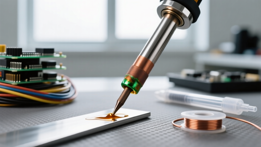
According to the Weller Tools Official Catalog, premium tips are not solid copper. Solid copper would dissolve into molten solder within hours. Instead, Weller utilizes an oxygen-free high-conductivity (OFHC) copper core for rapid heat transfer, electroplated with a 0.004 to 0.008-inch layer of iron. This iron plating provides the structural barrier against solder erosion. The non-working areas are coated in a chromium layer to prevent solder creep, while the working end is pre-tinned for immediate wetting.
Matching Geometry to the PCB Joint
The most common mistake among hobbyists and junior technicians is defaulting to a conical tip for all work. Conical tips possess a tiny surface area at the point of contact, resulting in high thermal resistance and poor heat transfer to the pad. Here is how to properly match Weller geometries to your specific soldering tasks.
1. Chisel Tips (e.g., ETA, RT4)
Best for: 80% of general-purpose soldering, through-hole components, and standard 0805/0603 SMD pads.
Technique: The flat face of a chisel tip maximizes surface area contact. When soldering a 0.1-inch header pin, place the flat edge against both the barrel and the pad simultaneously. The broad contact area ensures the flux activates evenly before the solder wire is introduced.
2. Bevel / Hoof Tips (e.g., B-series, RTW1)
Best for: Drag soldering SOIC and TQFP ICs, and scooping excess solder from tight pitches.
Technique: The concave bevel acts as a microscopic solder reservoir. Apply a small amount of solder to the bevel, add fresh flux to the IC leads, and drag the tip across the pins in a single, fluid motion. The surface tension of the molten solder will pull the alloy into the individual pads while leaving the spaces clear.
3. Knife Tips (e.g., RTW2, ET_K)
Best for: Cutting through solder bridges, cleaning up 0.4mm pitch QFN pads, and vertical access in cramped enclosures.
Technique: Use the sharp point of the knife for precision spot-heating on a single corner pin of a BGA, and use the flat edge of the blade for drag-soldering or scraping away oxidized flux residue.
4. Conical Tips (e.g., PTA7, RT1)
Best for: Extremely tight micro-vias, ultra-fine wire wrapping, and 01005 components.
Warning: Avoid using standard conical tips for heavy ground planes. The IPC J-STD-001 Standard strictly warns against extended dwell times, which are inevitable when a low-mass conical tip struggles to heat a high-mass ground via.
Thermodynamics and Temperature Profiling
Setting the correct temperature on your Weller station is a function of the solder alloy's melting point and the joint's thermal mass, not a 'more is better' dial. Cranking a WE1010NA to 450°C to compensate for a ground plane will instantly oxidize the tip and degrade the PCB's FR4 substrate.
- Leaded Alloys (Sn63/Pb37): Melts at 183°C. Set your Weller station to 315°C - 330°C. This provides enough thermal headroom for rapid wetting without scorching rosin-based fluxes.
- Lead-Free Alloys (SAC305): Melts at 217°C - 220°C. Requires a station setting of 350°C - 370°C. SAC alloys have poorer wetting characteristics, making the wide surface area of a chisel or bevel tip mandatory.
- High-Reliability / Automotive (Innolot): Melts around 217°C but requires higher thermal input due to complex joint structures. Set to 380°C and utilize XT series tips if the ground plane absorbs heat faster than an 80W RT tip can deliver it.
Expert Insight: The Weller closed-loop sensor is located at the very front of the heater, just millimeters from the tip base. When you apply the iron to a cold joint, the sensor detects the voltage drop and pulses maximum wattage to the heating element. If your tip is too small (e.g., an RT1 on a 10AWG wire), the heater will remain at 100% duty cycle, eventually triggering thermal shutdown or oxidizing the tip shank.
The 4-Step Weller Tip Maintenance Protocol
Tips are consumables, but premature death is usually the result of operator error. Adhering to high-reliability guidelines, such as those outlined in the NASA Workmanship Standards, can extend the life of a Weller RT or ET tip from a few weeks to several years.
Step 1: The 'Always Tinned' Rule
The iron plating on a Weller tip oxidizes rapidly when exposed to ambient air at 350°C. The moment you finish a joint, melt a generous blob of fresh, heavily fluxed solder onto the working end before placing it back in the holder. This sacrificial solder blob takes the oxidative damage, protecting the underlying iron layer. Wipe and re-tin immediately before the next joint.
Step 2: Abandon the Damp Sponge
Cellulose sponges are a relic of the past. Wiping a 360°C tip on a damp room-temperature sponge induces severe thermal shock. This rapid contraction causes micro-fractures in the iron plating, allowing molten solder to penetrate and dissolve the copper core (a failure mode known as 'coring'). Solution: Use dry brass wool (such as the Weller WHCC). Brass is softer than the iron plating, removing carbon and oxidized flux via mechanical friction without dropping the tip temperature.
Step 3: Chemical Flux Management
Water-soluble (organic acid) fluxes are highly aggressive. If you are using OA flux for plumbing or heavy-duty wire lugging, you must clean the tip with brass wool immediately after the joint is made. Leaving activated acid flux on a Weller tip for even five minutes will begin etching the iron plating.
Step 4: Proper Storage and Power Down
Never leave a Weller station powered on when unattended. If your station lacks an auto-sleep feature (like the older WES51), manually turn it off. For long-term storage, remove the tip from the heating element. Flux residue can carbonize and act as a thermal insulator between the heater and the tip barrel, leading to sensor calibration errors over time.
Troubleshooting Common Weller Tip Failures
Failure Mode 1: Tip Blackening (Non-Wetting)
Symptom: Solder balls up and rolls off the tip; the working surface turns dark grey or black.
Cause: High-temperature oxidation or burning of no-clean flux residues.
Fix: Do not use sandpaper or a file—this destroys the iron plating. Instead, use a specialized tip tinner (a mixture of phosphoric acid and solder powder). Dip the hot tip into the compound for 3-5 seconds, then wipe on brass wool and immediately apply fresh SAC305 solder.
Failure Mode 2: Pitting and Coring
Symptom: The surface of the tip feels rough, and small craters are visible under magnification.
Cause: Using lead-free solder at excessive temperatures (>400°C) or using highly active fluxes without cleaning. Lead-free alloys dissolve iron up to three times faster than leaded alloys.
Fix: The tip is permanently compromised and must be discarded. Prevent recurrence by lowering the idle temperature to 350°C and utilizing Weller's active heating technology to compensate for thermal load rather than relying on excessive baseline heat.
Failure Mode 3: Solder Creep up the Shaft
Symptom: Solder migrates past the working area and onto the chrome-plated shank, eventually seizing the tip inside the heating element.
Cause: Dipping the tip too deeply into the solder pool, or using a tip that has been physically scratched, breaching the chrome barrier.
Fix: Allow the station to cool completely. Apply penetrating oil to the shank and gently twist with pliers padded by a cloth. To prevent this, never submerge the tip past the bevel or chisel face.
Final Thoughts on Precision Soldering
Mastering Weller soldering iron tips requires shifting your perspective from viewing the iron as a simple heat source to treating it as a precision thermal delivery system. By matching the correct series (ET, RT, LT) to your station's wattage, selecting the appropriate geometry for the pad's thermal mass, and enforcing a strict brass-wool maintenance protocol, you will achieve consistent, IPC-compliant joints while drastically reducing your consumable overhead.