
The Reality of Cordless Thermal Management
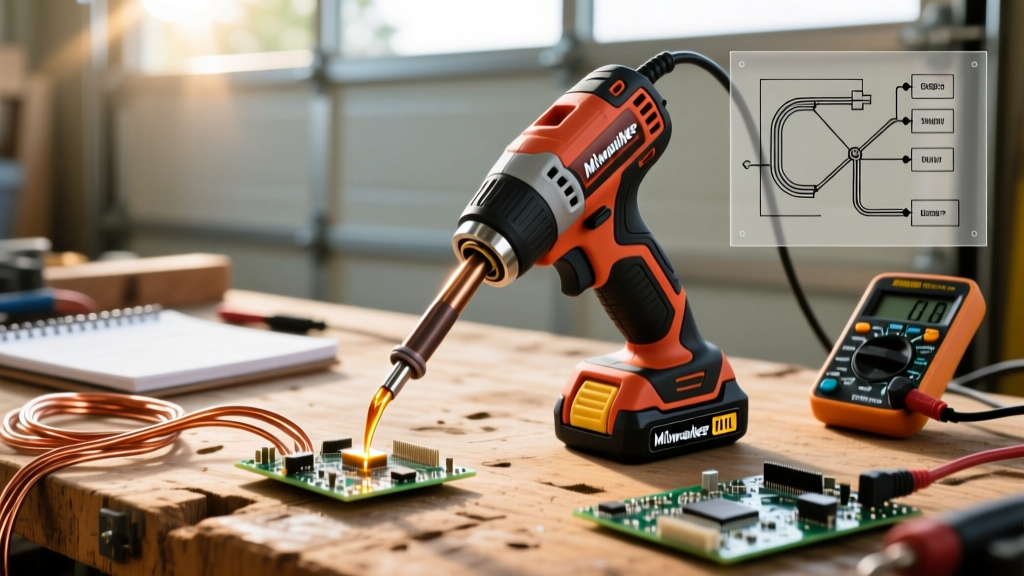
The transition from a tethered bench station to a portable setup fundamentally changes how you approach soldering. The Milwaukee M12 cordless soldering iron (specifically the 2475-20 bare tool and 2475-21 kit) has become a ubiquitous tool for HVAC technicians, automotive electricians, and field service engineers. Priced around $109 for the bare tool in 2026, it offers undeniable convenience. However, operating a cordless iron requires a complete paradigm shift in thermal management, battery physics, and joint preparation. Unlike closed-loop bench stations that constantly adjust power to maintain a set temperature, the M12 platform operates on a fixed thermal profile, demanding that the technician compensate for variables through technique rather than dial adjustments.
Understanding the Milwaukee 2475-20 Thermal Profile
The Milwaukee 2475-20 reaches its operating temperature of 780°F (415°C) in approximately 18 seconds. This rapid heat-up is achieved through a high-current draw from the M12 battery, feeding a thick-film heating element. Because the iron lacks digital temperature control, you cannot simply turn the dial down to 600°F for sensitive components or crank it to 850°F for heavy ground planes. You are locked into the 780°F ceiling. Therefore, your primary method of controlling heat transfer is contact time and tip geometry.
Expert Insight: Fixed-temperature cordless irons rely heavily on the thermal mass of the tip itself. When the tip touches a large copper pad, the temperature at the very edge of the tip drops instantly. The iron's recovery time dictates your maximum joint size. If you hold the iron too long waiting for the solder to flow, you risk pad delamination or wire insulation melt-back.
Managing Battery Voltage Sag and Thermal Recovery
One of the most misunderstood aspects of the Milwaukee M12 cordless soldering iron is how battery selection impacts thermal recovery. Lithium-ion cells experience voltage sag under high continuous current draw. When the iron's heating element demands maximum current to recover from a cold 10 AWG wire splice, a smaller battery will struggle.
- M12 2.0Ah CP (Compact): Ideal for quick, light-duty splices on 18-22 AWG signal wires. Expect noticeable thermal lag when moving to consecutive joints.
- M12 4.0Ah XC (Extended Capacity): The sweet spot for field technicians. The lower internal resistance allows for sustained current delivery, keeping the heating element energized during heat-sink events.
- M12 High Output 6.0Ah: Necessary for heavy automotive wiring or thick HVAC control board ground planes. The advanced cell chemistry minimizes voltage sag, ensuring the iron recovers to 780°F almost instantly between joints.
Tip Selection and Application Matrix
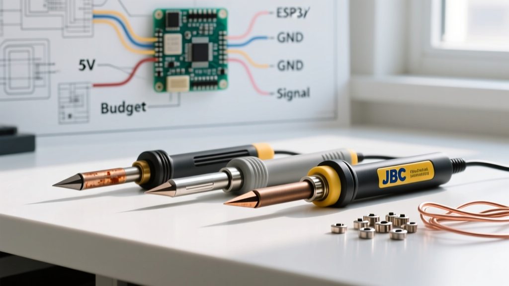
Because you cannot adjust the temperature, you must adjust the surface area. Selecting the correct tip geometry is the most critical decision you will make before striking an arc or splicing a wire. Below is a decision matrix for field applications.
| Tip Geometry | Best Field Application | Thermal Transfer Rate | Technique Note |
|---|---|---|---|
| Fine Conical | 18-24 AWG sensor wires, tight automotive harnesses | Low | Requires precise placement; high risk of oxidation if left untinned. |
| Standard Chisel (3/16 in.) | 12-16 AWG power wires, standard PCB through-hole | Medium-High | Maximize contact by laying the flat side against the wire barrel. |
| Wide Chisel / Bevel | 8-10 AWG battery cables, heavy ground plane lugs | High | Essential for overcoming massive thermal mass; requires XC or HO battery. |
Cold Weather Field Operations
When repairing outdoor HVAC control boards or automotive wiring in sub-40°F (4°C) environments, the fixed 780°F ceiling of the Milwaukee M12 cordless soldering iron becomes a bottleneck. The ambient cold acts as a massive heat sink, pulling thermal energy away from the joint faster than the cordless element can replenish it. To counteract this, field technicians must employ localized pre-heating. While you might not have a benchtop pre-heater in a service van, using a standard M18 heat gun on a low setting for 5 to 10 seconds before applying the iron can raise the local ambient temperature of the wire and pad. This drastically reduces the thermal delta the soldering iron must overcome.
Furthermore, switching from standard rosin-core wire solder to a mildly activated no-clean gel flux lowers the surface tension of the molten alloy faster. This promotes rapid wetting even when the iron is struggling to maintain peak temperature against the cold ambient air.
Step-by-Step Field Repair Workflow
Adhering to industry standards ensures reliability, especially when you cannot rely on the visual feedback of a digitally controlled station. According to the IPC J-STD-001 standard, proper wetting and thermal limits must be respected to prevent latent field failures. Follow this optimized workflow for the M12 iron:
- Mechanical Preparation: Never rely on solder for structural strength. Create a secure Western Union splice or crimp connection first. Strip the wire cleanly to avoid nicking the copper strands, which creates localized resistance hotspots.
- Flux Application: Apply a high-quality no-clean flux (such as Kester 245 or Amtech NC-559) to the mechanical joint. In field environments, extra flux compensates for minor oxidation and accelerates the wetting process, saving crucial battery life.
- Iron Placement: Press the flat of the chisel tip against the joint at a 45-degree angle. Do not touch the solder to the iron tip first; this creates a heat bridge that often results in a cold joint if the flux burns off before reaching the wire.
- Solder Feed: Apply 60/40 or SAC305 solder to the opposite side of the joint from the iron. When the copper reaches the melting point of the alloy, the flux will activate, and the solder will be drawn through the joint via capillary action.
- Inspection: As outlined in the NASA Workmanship Standards, a proper solder joint must exhibit a smooth, concave fillet with visible wire contours. A dull, gray, or bulbous joint indicates insufficient heat transfer or movement during the cooling phase.
Limitations: When NOT to Use the M12
While the Milwaukee M12 cordless soldering iron is a powerhouse for wire splicing and heavy-duty field repairs, it is not a universal replacement for a bench station. Avoid using this tool in the following scenarios:
- SMD Rework: The lack of precise temperature control and the high thermal mass of the M12 tips make it highly dangerous for 0402, 0603, or even 0805 surface mount components. You risk lifting pads or melting adjacent plastic connectors.
- Multi-Layer PCB Ground Planes: If you are repairing a 4-layer or 6-layer control board with heavy internal copper pours, the M12 will likely fail to deliver enough continuous thermal energy to achieve proper through-hole wetting, resulting in dangerous cold solder joints.
- Heat-Sensitive Semiconductors: Components like MOSFETs or sensitive sensors that require strict temperature profiling should only be soldered with a closed-loop station equipped with micro-tips.
Final Thoughts on Tip Maintenance
The proprietary tips on the 2475-20 are prone to rapid oxidation if abused. Because the iron lacks an automatic sleep mode on older firmware revisions, leaving it powered on while you strip wires will quickly burn the iron plating off the tip. Always keep a damp brass sponge nearby, clean the tip immediately after every joint, and apply a heavy coat of fresh solder before sliding the battery out. Treat the thermal mass of your tip as a consumable resource, and the Milwaukee M12 cordless soldering iron will remain a reliable partner in the harshest field conditions.