
The Physics of Convection Rework
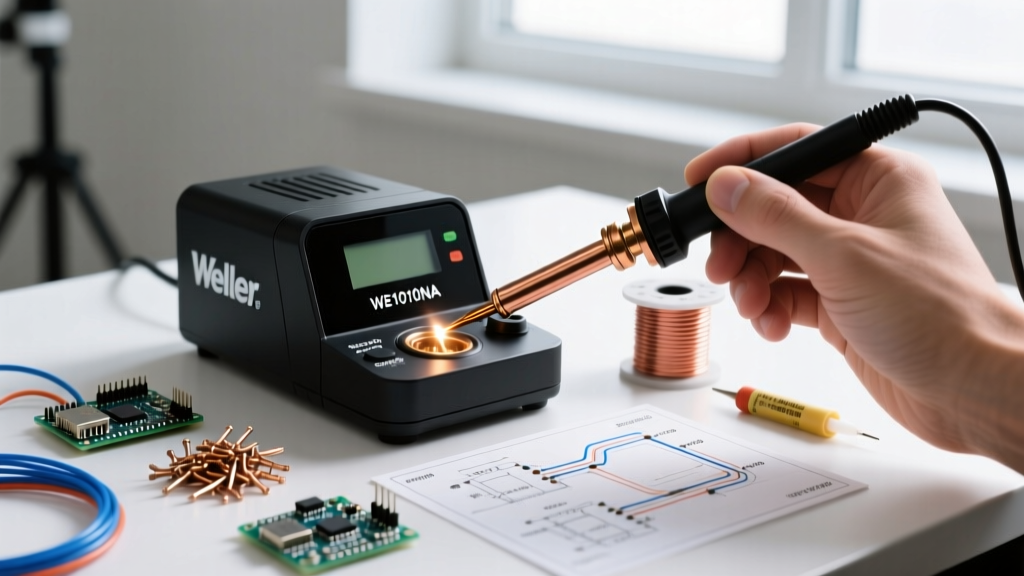
Surface-mount technology (SMT) dominates modern PCB design, with component densities pushing into microscopic territories. While a traditional soldering iron relies on conduction, a hot air gun soldering station utilizes forced convection to transfer thermal energy. Air is inherently a poor thermal conductor compared to copper or aluminum; therefore, successful rework requires compensating with precise airflow volume (measured in liters per minute, or L/min) and targeted thermal profiling. Applying high heat with low airflow will scorch component packages and lift FR4 pads, while low heat with high airflow will result in cold solder joints and incomplete reflow.
According to the Texas Instruments QFN/SON Packaging Application Note, the thermal mass of the PCB ground planes acts as a massive heat sink. When reworking a Quad Flat No-lead (QFN) package with an exposed thermal pad, the station must deliver enough convective energy to overcome this sink without exceeding the component's maximum thermal rating (typically 260°C for 10 seconds on the package body). Understanding this balance is the cornerstone of professional SMD rework.
Selecting the Right Hot Air Gun Soldering Station
Not all stations are engineered for precision micro-soldering. Entry-level models often suffer from temperature overshoot and inaccurate airflow sensors. For serious rework in 2026, brushless fan motors and closed-loop PID temperature controllers are mandatory. Below is a comparison of the industry-standard stations used by professional repair technicians and engineering labs.
| Station Model | Max Power | Airflow Range | Price Range (2026) | Best Use Case |
|---|---|---|---|---|
| Quick 861DW | 1200W | 1 - 120 L/min | $360 - $400 | General SMD, QFN, SOIC rework |
| Hakko FR-830 | 630W | 1 - 50 L/min | $550 - $600 | Precision micro-soldering, 0201 passives |
| JBC JTSE-2B | 1300W | 2 - 110 L/min | $800 - $850 | High-volume production, heavy ground planes |
The Quick 861DW remains the undisputed workhorse for independent technicians due to its rapid heat recovery and vast ecosystem of third-party nozzles. However, for ultra-fine pitch components where localized heat is critical, the Hakko FR-830 offers superior airflow stability at lower volumes.
Thermal Profiles by Component Package
There is no universal 'set-and-forget' temperature. Your profile must adapt to the component's physical dimensions, the solder alloy (Sn63/Pb37 melts at 183°C; SAC305 lead-free melts at 217°C), and the PCB layer count. The following matrix provides baseline starting points for leaded solder rework on standard 2-layer to 4-layer FR4 boards.
| Component Type | Nozzle Size | Temperature | Airflow | Dwell Time |
|---|---|---|---|---|
| 0402 / 0603 Passives | 3mm - 5mm Round | 300°C - 320°C | 20 - 30 L/min | 3 - 5 seconds |
| SOIC-8 / SOP-16 | 10mm - 14mm Square | 320°C - 340°C | 40 - 50 L/min | 10 - 15 seconds |
| QFN-32 / QFN-48 | 8mm - 12mm Square | 340°C - 360°C | 50 - 70 L/min | 20 - 40 seconds |
| BGA (Requires Preheat) | Custom BGA Nozzle | 350°C - 380°C | 60 - 80 L/min | 60 - 120 seconds |
Expert Insight: Always increase airflow before increasing temperature. High airflow at a moderate temperature (e.g., 340°C at 70 L/min) penetrates under component bodies far more effectively than low airflow at extreme temperatures (e.g., 400°C at 20 L/min), which simply burns the flux and oxidizes the pads.
Step-by-Step QFN Rework Technique
QFN packages are notoriously difficult due to their hidden perimeter leads and large central thermal pad. The IPC-7711/7721 Rework, Modification and Repair Standard emphasizes the importance of pad planarization and flux activation prior to component placement. Follow this precise workflow for reliable results.
Phase 1: Preparation and Thermal Shielding
- Clean the Area: Use isopropyl alcohol (99% IPA) and a lint-free swab to remove surface contaminants.
- Apply Tacky Flux: Dispense a small amount of Amtech NC-559-V2-TF or Chip Quik SMD291AX tacky flux around the perimeter of the QFN. Do not over-apply; excess flux will boil and cause component shifting.
- Shield Surrounding Components: Apply Kapton (polyimide) tape and aluminum foil tape to protect adjacent plastic connectors and sensitive ICs from convective heat exposure.
Phase 2: Targeted Heating and Extraction
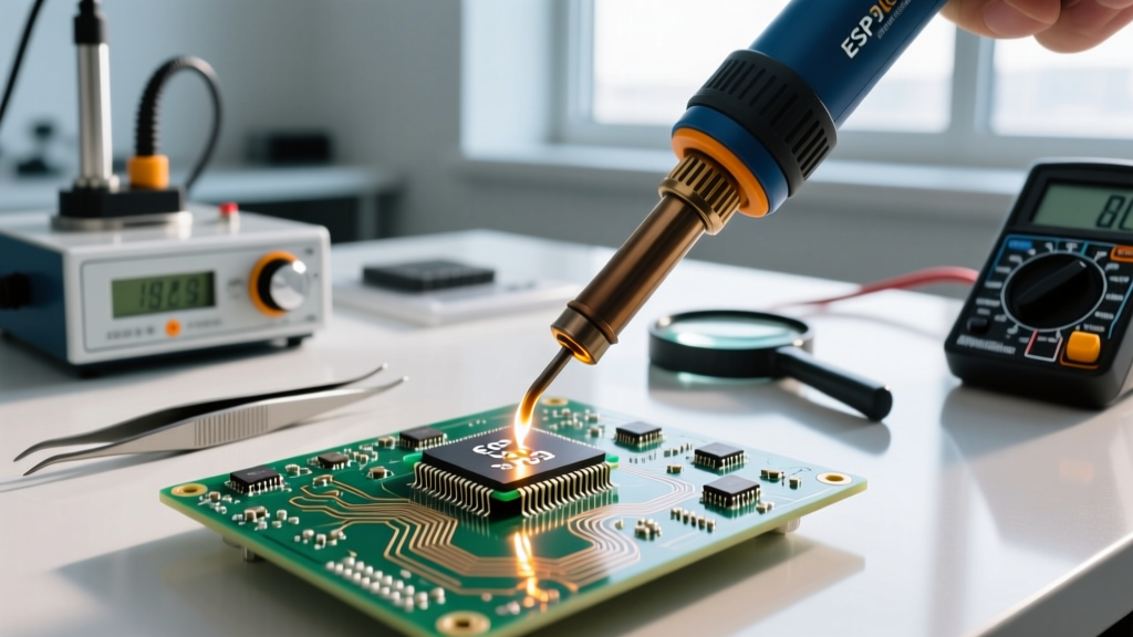
Set your hot air gun soldering station to 350°C with airflow at 60 L/min. Hold the nozzle approximately 10mm to 15mm above the PCB. Use a continuous, slow circular motion to distribute heat evenly across the package. Never hold the gun stationary. After 20-30 seconds, gently nudge the component with Vetus ST-11 anti-magnetic tweezers. When the surface tension of the molten solder breaks and the component 'floats', lift it straight up. Avoid pulling at an angle, which will tear the copper pads off the FR4 substrate.
Phase 3: Pad Planarization (Wicking)
Once the IC is removed, the pads will have uneven solder mounds. Apply a generous layer of liquid flux and place a Chemtronics Type S (80-10-10) desoldering wick over the pads. Using a flat-tip soldering iron set to 320°C, gently drag the iron over the wick. The capillary action will absorb the excess solder, leaving a perfectly flat, coplanar pad surface. Clean the area thoroughly with IPA and a soft-bristle brush.
Phase 4: Placement and Reflow
Apply a microscopically thin layer of fresh tacky flux to the cleaned pads. Using tweezers, align the QFN to the silkscreen outline. The tackiness of the flux will hold it in place. Switch your hot air gun to a slightly lower airflow (40 L/min) to prevent blowing the lightweight component out of alignment. Heat evenly until the solder reflows and the component visibly 'snaps' into its final position due to surface tension alignment. Allow the board to cool naturally; do not use compressed air to force-cool the joint, as this induces micro-cracking in the solder lattice.
Critical Failure Modes and Mitigation
Even with premium equipment, technique errors lead to catastrophic board damage. Recognize these common failure modes:
- Pad Lifting (Thermal Shock): Caused by prying a component before the central thermal pad has fully liquefied. Mitigation: Use a board preheater (like the Hakko FR-872 set to 120°C) to reduce the thermal delta between the top and bottom of the PCB.
- Tombstoning on Passives: Occurs when one pad heats faster than the other, causing the surface tension to pull the component upright. Mitigation: Ensure your circular heating pattern is perfectly centered and symmetrical over the component body.
- Plastic Connector Melting: Hot air reflects off ground planes and can melt adjacent headers. Mitigation: Never rely solely on Kapton tape for thermal insulation. Use thick aluminum copper tape, which reflects convective heat and acts as a physical heat sink.
- Solder Balling / Bridging: Caused by expired solder paste or flux that has lost its volatile activators. Mitigation: Store all solder pastes and tacky fluxes in a dedicated refrigerator and allow them to reach room temperature before opening the jar to prevent condensation contamination.
Summary
Mastering a hot air gun soldering station requires shifting your mindset from direct contact heating to fluid dynamics and thermal mass management. By selecting the correct nozzle geometry, respecting the thermal limits of component packages, and strictly adhering to pad planarization protocols, you can achieve factory-grade SMD rework on your bench. Invest in quality flux, maintain your station's air filters, and always validate your thermal profiles on scrap boards before attempting rework on mission-circuitry.