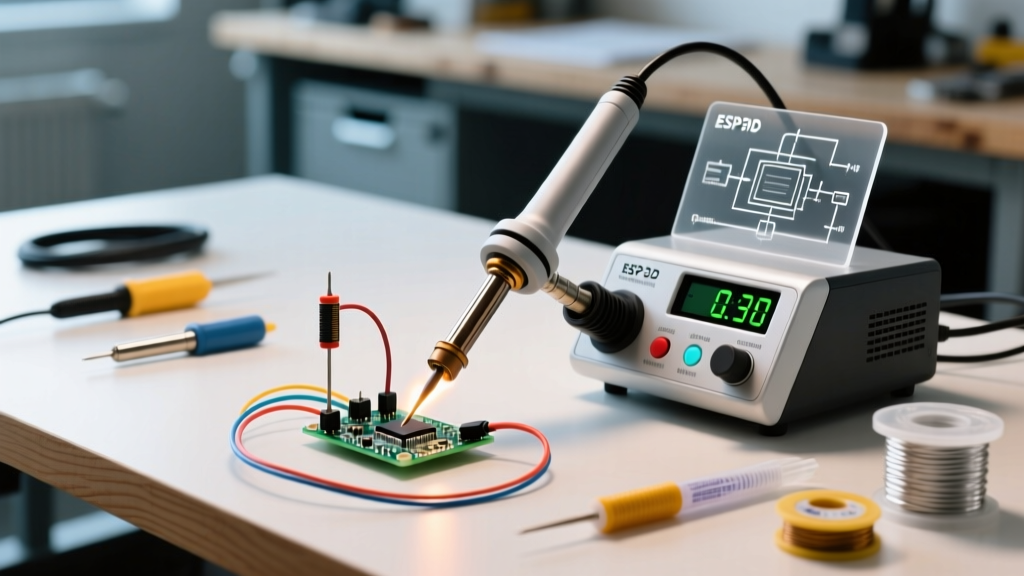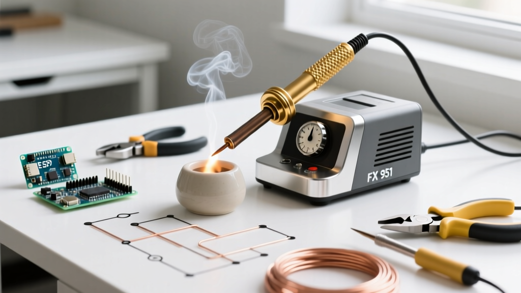

The Hakko FX-951 Architecture: Why It Remains an Industry Standard
Even as we navigate the electronics manufacturing landscape of 2026, the Hakko FX-951 soldering station remains a cornerstone in both professional assembly houses and advanced DIY labs. Operating at 70 watts and utilizing a 24V AC output, the FX-951 delivers rapid thermal recovery that outpaces many newer, digitally branded competitors. However, owning a premium station is only half the battle; extracting peak performance requires a deep understanding of its composite heater technology, precise calibration protocols, and strict maintenance regimens.
Unlike older transformer-based stations that rely on separate thermocouples and heating elements, the FX-951 utilizes the T18 tip series. These tips feature a ceramic heater and temperature sensor embedded directly inside the tip assembly. This design minimizes thermal lag, allowing the station to sense a temperature drop the moment the tip touches a copper pad, and immediately surge power to compensate. According to the IPC J-STD-001 standards, maintaining strict thermal profiles is critical to preventing intermetallic compound (IMC) overgrowth, which can lead to brittle solder joints. The FX-951's rapid recovery keeps dwell times well under the recommended maximums, but only if the system is correctly calibrated and maintained.
Optimizing Thermal Mass: T18 Tip Selection Strategies
A common mistake among intermediate users is defaulting to fine conical tips (like the T18-B) for all surface-mount work, under the assumption that smaller tips offer better precision. In reality, conical tips have very low thermal mass at their apex, leading to severe temperature drops when soldering ground planes or high-pin-count ICs.
Matching Geometry to the Task
- T18-D24 (Chisel, 2.4mm): The ultimate workhorse. The flat surface area provides excellent thermal transfer for 0805 to 1206 SMD components and standard through-hole leads. The chisel shape allows you to use the edge for fine work and the flat face for dragging solder.
- T18-K (Knife): Ideal for drag-soldering QFP and SOP ICs. The knife edge can be dragged across pins, while the heel of the blade holds enough thermal mass to melt solder paste or flux-cored wire instantly.
- T18-IL (Mini-Hook): Reserved for ultra-fine 0402 or 0201 components and tight-pitch rework where a standard chisel would bridge adjacent pads.
When working with multi-layer PCBs featuring heavy internal copper pours, always select the largest tip geometry that will physically fit on the pad. The FX-951's 70W heater can only push heat as fast as the tip's physical mass can transfer it.
Step-by-Step Calibration Guide
Over time, the internal resistance of the ceramic sensor can drift, or you may notice a discrepancy between the station's digital display and the actual tip temperature. Calibrating the FX-951 requires a reliable tip thermometer (such as the Hakko 191 or a high-grade K-type thermocouple probe).
- Preparation: Insert a fresh, genuine T18-D24 tip and allow the station to heat up to 350°C (662°F). Let it stabilize for at least three minutes.
- Enter Calibration Mode: Turn the power switch OFF. Press and hold the '*' (Enter) button on the front panel, then turn the power switch ON while continuing to hold the button.
- Read the Offset: The digital display will now show the current temperature offset value (e.g., +05 or -03).
- Measure: Place your tip thermometer sensor directly against the flat face of the T18 tip. Wait for the thermometer reading to stabilize.
- Adjust: If the thermometer reads 345°C but the station is set to 350°C, you have a -5°C variance. Use the UP/DOWN arrows to adjust the offset value on the FX-951 display until it compensates for this exact difference.
- Save and Exit: Press the '*' button to lock in the new calibration offset, then power cycle the station.
Expert Warning: Never calibrate the station using a worn or oxidized tip. A degraded tip will insulate the thermometer probe, resulting in an incorrect offset that will cause the station to overcompensate and overheat fresh tips later.
Decoding FX-951 Error Codes and Failure Modes
The FX-951 features built-in diagnostics that halt power to the handpiece when anomalies are detected. Understanding these codes is vital for rapid troubleshooting on the bench.
| Error Code | Meaning | Root Cause & Resolution |
|---|---|---|
| H-E | Heater Error | The ceramic heater circuit is open. Usually caused by a broken wire in the handpiece cord or a burnt-out heater. Replace the B2272 heater/sensor assembly (approx. $38 in 2026). |
| S-E | Sensor Error | The temperature sensor is shorted or reading out of bounds. Often triggered if the tip is removed while the station is powered on. Power cycle the unit. If it persists, check for solder splatter bridging the handpiece connector pins. |
| C-E | Calibration Error | The internal EEPROM has detected a corrupted offset value, or the calibration button is stuck. Perform a hard reset by holding the UP and DOWN arrows simultaneously while powering on to restore factory defaults. |
The Counterfeit Tip Crisis of 2026
As supply chains have shifted, the market has been inundated with counterfeit T18 tips selling for $2 to $4 each on major e-commerce platforms. While visually identical to genuine Hakko tips, counterfeits pose a severe risk to both your work and your equipment.
Genuine T18 tips feature a proprietary iron plating process over a high-purity copper core, ensuring uniform thermal conductivity. Counterfeits often use low-grade steel alloys with poor thermal transfer. When the FX-951's sensor detects that the counterfeit tip isn't heating up fast enough, the 70W heater stays engaged at maximum duty cycle. This extreme thermal stress frequently cracks the ceramic heater element inside the handpiece, turning a $12 tip savings into a $45 handpiece repair. Always source tips from authorized distributors and verify the laser-etched Hakko logos and lot numbers.
Maintenance: Thermal Shock and Oxidation Management
How you clean your tip dictates its lifespan. The traditional wet cellulose sponge method, while ubiquitous, is highly detrimental to the FX-951's composite tips.
The Danger of Wet Sponges
When a 350°C tip touches a wet sponge, the surface temperature plummets by over 150°C in milliseconds. This violent thermal contraction causes micro-fractures in the iron plating. Over a few weeks, these micro-cracks allow molten solder to penetrate the plating and dissolve the underlying copper core, ruining the tip. Furthermore, the constant thermal shock degrades the ceramic heater bond.
The Brass Wool Alternative
Switch to a dry brass wire sponge (like the Hakko 599B). Brass is softer than the iron plating on the tip, meaning it will scrape away oxidized flux and excess solder without scratching the tip surface. More importantly, brass wool only drops the tip temperature by 10°C to 15°C, keeping the station within its optimal thermal recovery window and aligning with the strict thermal management guidelines outlined in the NASA Workmanship Standards for high-reliability soldering.
Long-Term Storage and End-of-Day Protocols
Never leave the FX-951 powered on when not in use; the continuous heat will rapidly oxidize the tip, turning it black and un-tinnable. However, how you power it down is equally important.
The Tinning Protocol: Before turning off the power switch, melt a generous amount of rosin-core solder onto the tip, creating a large, shiny blob that completely covers the working surface. This sacrificial layer of solder will oxidize instead of the tip's iron plating while the unit cools down. When you power the station back on the next day, simply wipe the oxidized solder blob into your brass wool, and you will be left with a pristine, perfectly tinned tip ready for immediate use.
Conclusion: Protecting Your Investment
The Hakko FX-951 is a precision instrument disguised as a rugged workhorse. By adhering to strict calibration schedules, abandoning wet sponges in favor of brass wool, and refusing to compromise with counterfeit tips, you ensure that your station will easily survive a decade of daily use. For further reading on maintaining optimal soldering profiles for advanced PCB assemblies, refer to the official Hakko FX-951 documentation and industry-standard workmanship guidelines.