
The Anatomy of Stick Drift: Why Tip Geometry Matters
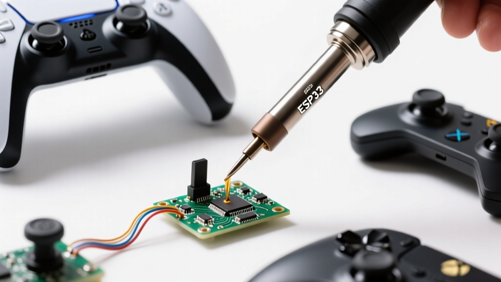
When technicians and hobbyists search for the ideal joystick soldering iron tip, they are almost exclusively targeting a highly specific repair scenario: replacing analog stick potentiometers on modern game controllers. Whether you are fixing stick drift on a PS5 DualSense, an Xbox Elite Series 3, or a Steam Deck OLED, the underlying culprit is usually the ALPS Alpine RKJXU series 14-pin joystick module. Over time, the carbon wiper tracks inside these modules degrade, leading to the phantom inputs that plague the gaming industry. As iFixit's extensive teardowns and repair investigations have highlighted, stick drift is a systemic hardware flaw that requires precision micro-soldering to resolve permanently.
However, selecting the right joystick soldering iron tip is not as simple as grabbing the smallest needle-point you can find. The 14-pin footprint of an ALPS joystick module is a hybrid nightmare: it features ten tiny surface-mount device (SMD) signal pins spaced at roughly 1.2mm pitch, surrounded by four massive through-hole structural anchor tabs connected to internal ground planes. A single tip cannot efficiently handle both the delicate SMD pins and the high-thermal-mass grounding tabs. This deep dive explores the exact micro-tips, thermal strategies, and dual-tip workflows required for flawless controller repairs in 2026.
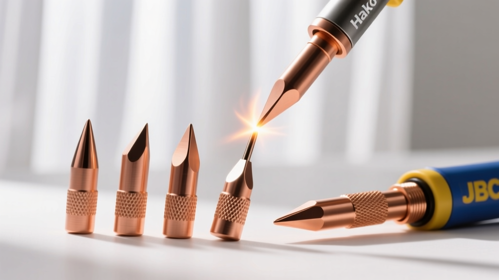
Top Contenders: Evaluating Micro-Tips for ALPS Joystick Modules
To successfully solder the inner SMD pins without bridging the pads or lifting the PCB traces, you need a tip with high thermal recovery, a fine point, and an optimized wetting surface. Below is a comparison of the industry-standard micro-tips used by professional console repair technicians.
| Tip Model | Geometry & Size | 2026 Avg. Price | Thermal Recovery | Best Application on Joystick Module |
|---|---|---|---|---|
| JBC C210-105 | Bent Conical (0.5mm) | $52.00 | Exceptional (2 sec) | SMD signal pins, tight clearance drag soldering |
| Weller RTW013S | Micro Chisel (0.13 x 0.4mm) | $48.00 | Excellent (3 sec) | Precision tinning of individual SMD pads |
| Hakko T18-B2 | Conical (1.0mm) | $11.50 | Moderate (6 sec) | General through-hole, too thick for inner SMD pins |
| Pine64 TS-I10 | Bent Conical (0.5mm) | $18.00 | Good (4 sec) | Budget-friendly SMD pin rework |
For professional results, the JBC C210-105 remains the undisputed champion for the SMD portion of the joystick module. The 45-degree bent conical shape allows you to rest the shaft of the tip against the PCB for stability while the 0.5mm point precisely transfers heat to the 1.2mm pitch pads. The Weller RTW013S micro-chisel is a close second, offering a slightly broader contact patch that excels at drag soldering when paired with high-quality tacky flux.
The Dual-Tip Strategy: Solving the Heat Sink Dilemma
The most common mistake beginners make when searching for a joystick soldering iron tip is assuming one tip can do the entire job. The four outer structural tabs on the ALPS module are mechanically stamped and soldered directly to the controller's internal ground planes. These planes act as massive heat sinks.
Expert Insight: Attempting to melt the ground tabs with a micro-tip like the C210-105 will result in cold solder joints, prolonged dwell times, and catastrophic PCB delamination. You must use a dual-tip or hybrid approach.
The Recommended Arsenal
- Tip 1 (SMD Pins): JBC C210-105 (or equivalent 0.5mm bent conical) on a precision station like the JBC CD-2BQF.
- Tip 2 (Anchor Tabs): JBC C245-945 (2.2mm chisel) or a Hakko FX-951 with a T18-D24 chisel. Alternatively, a hot air rework station set to 380°C with a 4mm nozzle is preferred for the anchor tabs to avoid localized thermal stress.
Step-by-Step: Soldering the 14-Pin Joystick Potentiometer
Adhering to the micro-soldering guidelines outlined in the IPC-7711/7721 standards for rework and modification, follow this precise workflow to ensure long-term reliability and prevent damage to the controller's mainboard.
- Preparation & Low-Melt Alloy: Apply a generous amount of Amtech NC-559-V2-TF tacky flux to the existing 14 pins. Add 63/37 bismuth-based low-melt solder (melting point ~138°C) to the factory lead-free joints. This lowers the overall melting temperature, preventing pad lifting during desoldering.
- Desoldering: Use a high-thermal-mass chisel tip (or hot air) to melt the four ground tabs while simultaneously using flush cutters or a desoldering braid to clear the ten SMD pins. Remove the faulty module.
- Pad Leveling: Clean the PCB pads with 99% isopropyl alcohol (IPA) and desoldering wick. The pads must be perfectly flat; any residual solder bumps will prevent the new ALPS Alpine potentiometer from seating flush.
- Flux & Placement: Apply a thin, even layer of no-clean flux. Seat the new joystick module. Ensure the alignment pegs click into the PCB holes.
- SMD Pin Soldering: Switch to your micro-tip (e.g., C210-105). Set the station to 340°C. Using 0.3mm diameter Sn63Pb37 solder wire, touch the pad and the pin simultaneously. Dwell time should not exceed 1.5 seconds per pin to prevent heat from migrating into the module's internal carbon tracks.
- Anchor Tab Soldering: Switch to your heavy chisel tip or hot air. Flow standard 63/37 solder into the four structural holes until a proper fillet forms. Do not overfill, as excess solder can interfere with the controller's plastic housing reassembly.
Common Failure Modes When Using the Wrong Tip
Using an improperly sized joystick soldering iron tip introduces several critical failure modes that can permanently ruin a $70 controller mainboard:
- Pad Delamination: Using a low-wattage iron with a needle tip on the ground tabs forces the technician to hold the iron in place for 10+ seconds. This prolonged heat exposure breaks down the FR-4 epoxy resin, causing the copper pad to peel away from the fiberglass substrate.
- Solder Bridging: Using a conical tip that is too thick (like a 1.6mm bevel) on the 1.2mm pitch SMD pins will inevitably drag solder across adjacent pads, shorting the X/Y axis wiper signals and causing immediate, erratic stick drift.
- Flux Carbonization: If a tip lacks proper thermal recovery, the technician will compensate by turning the station up to 420°C+. This burns the rosin-based flux into a hard, conductive carbon residue. If this residue seeps into the open seams of the joystick module, it will cause electrical leakage and worse drift than the original faulty part.
Expert Verdict: Building Your Micro-Soldering Arsenal
There is no single 'magic' joystick soldering iron tip that handles every aspect of analog stick repair. True expertise lies in recognizing the hybrid nature of the ALPS module and adapting your tools accordingly. For the delicate SMD signal pins, invest in a high-end micro-conical tip like the JBC C210-105 or Weller RTW013S, paired with a station capable of sub-3-second thermal recovery. For the structural ground tabs, rely on high-thermal-mass chisels or convective hot air. By mastering this dual-tool approach and strictly controlling your dwell times and solder alloys, you can permanently eradicate stick drift and restore precision control to modern gaming hardware.