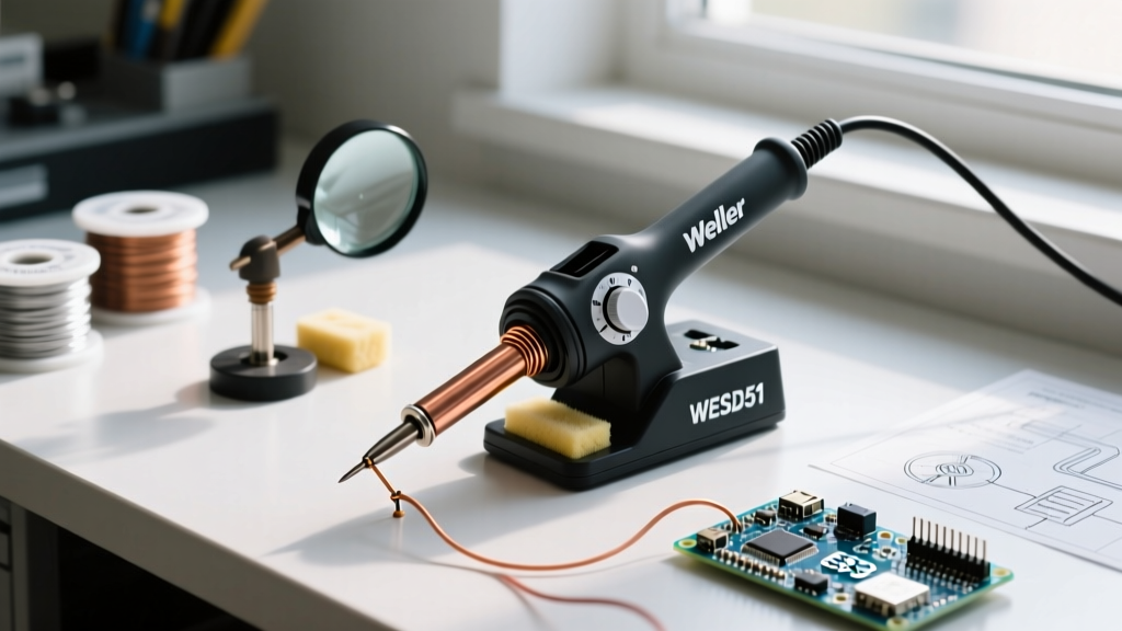

The Reality of Factory Calibration and Thermal Delta
The assumption that a digital display guarantees precise thermal transfer is a leading cause of cold solder joints, tombstoning, and lifted PCB pads. When you set a modern soldering station to 350°C, you are commanding the internal thermocouple sensor, not the tip surface. Because the sensor is buried inside the ceramic heating element—often 10mm to 15mm away from the tip apex—a thermal gradient naturally exists. This means your display might read 350°C while the actual working surface is only outputting 325°C.
According to the IPC J-STD-001 standards for soldered electrical assemblies, thermal profiles must account for the specific thermal mass of the connection and the tip. A factory-calibrated station is tested in a controlled vacuum environment with a standardized dummy load. In your 2026 workbench environment, ambient drafts, tip oxidation, and flux residue alter the thermal transfer coefficient. Calibrating your soldering iron heat via manual offset adjustments bridges the gap between the internal sensor reading and the true surface temperature.
Essential Calibration Hardware
Before adjusting any software offsets, you need accurate surface temperature measurements. Relying on a standard multimeter thermocouple is a critical mistake. Standard K-type bead probes act as massive heat sinks, drawing thermal energy away from micro-tips and yielding false low readings.
Dedicated Soldering Thermometers vs. Multimeters
- Hakko FG-100B (Approx. $185): The industry standard. The Hakko FG-100 utilizes a specialized, spring-loaded surface probe designed to apply exactly 100 grams of pressure to the tip. This ensures consistent thermal contact without artificially cooling the heating element.
- Fluke 87V with K-Type Adapter (Approx. $450+): While the Fluke 87V is an exceptional industrial multimeter, its standard K-type thermocouple is too thick for precision tip calibration. If you must use a multimeter, you need a specialized surface-contact thermocouple with a flat, low-mass junction, and you must apply a thermal compound (like silicone heat sink paste) between the probe and the tip to eliminate air gaps.
Pro-Tip: Always apply a small blob of leaded solder (e.g., 63/37 Sn/Pb) to the tip before pressing the thermocouple probe against it. The molten solder acts as a liquid thermal bridge, eliminating microscopic air gaps that cause severe temperature reading drops.
Step-by-Step Calibration Procedures by Station
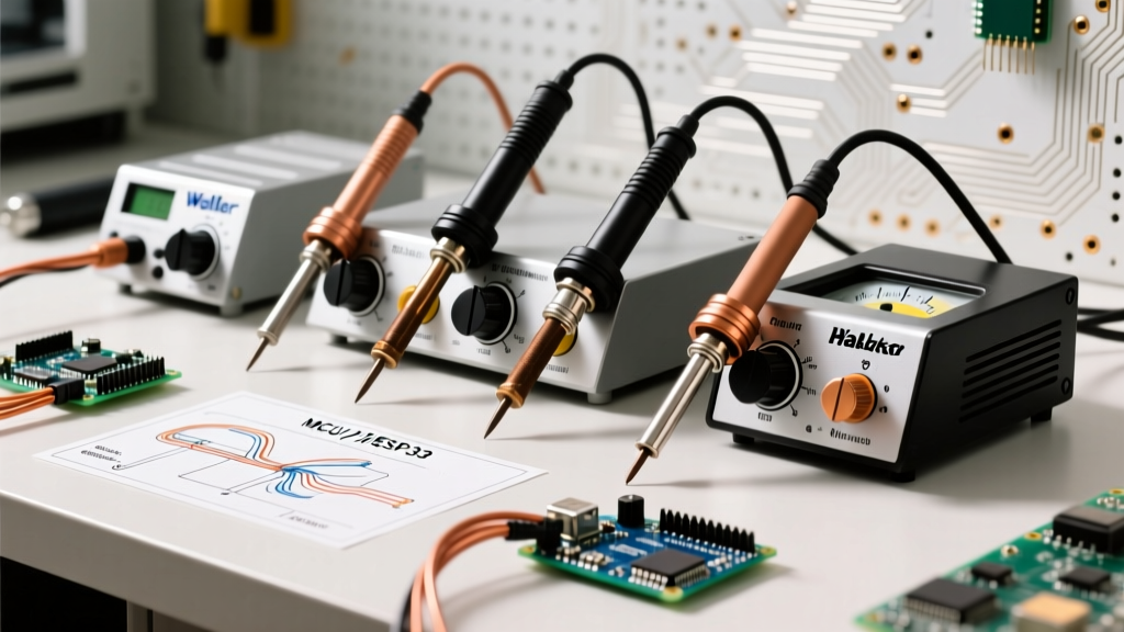
Different manufacturers handle thermal offset corrections differently. Below are the exact procedures for the three most common architectures in professional and prosumer labs.
1. Hakko FX-888D: The Three-Channel Offset Method
The FX-888D allows you to calibrate three distinct temperature points (C1, C2, C3) to create a basic thermal curve.
- Turn the station off. Press and hold the UP arrow button while turning the power switch on.
- The display will prompt for a password. Enter 888 using the UP/DOWN and ENTER buttons.
- Select C1 (Low range, typically 200°C). Set the station to 200°C, allow it to stabilize for 60 seconds, and measure the tip with your FG-100B.
- If the FG-100B reads 192°C, enter an offset of +008 into the C1 channel.
- Repeat for C2 (Mid range, 300°C) and C3 (High range, 400°C). Save and exit by holding the ENTER button for 3 seconds.
2. Weller WE1010: Single-Point Global Offset
Weller’s WE series uses a simpler, single-point global offset calculation. This is highly effective if you primarily work within a narrow temperature band (e.g., 340°C to 360°C for standard SAC305 lead-free solder).
- Press and hold the MENU and DOWN buttons simultaneously for 3 seconds to enter the calibration menu.
- Navigate to the CAL screen. The display will show the current internal sensor reading.
- Set the station to your primary working temperature (e.g., 350°C). Wait for the thermal recovery LED to stabilize.
- Measure the tip surface. Use the UP/DOWN arrows to input the exact delta. If your probe reads 342°C, adjust the offset to +8.
- Press ENTER to commit the new baseline to the EEPROM.
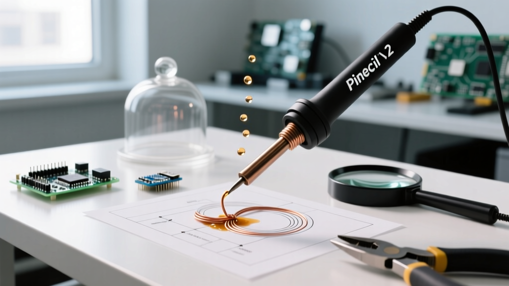
3. Pinecil V2 (IronOS): The Open-Source 4-Point Curve
For users running the open-source IronOS firmware on RISC-V based irons like the Pinecil V2, calibration is incredibly granular. IronOS uses a 4-point interpolation curve rather than a static offset.
- Power on the Pinecil while holding the Front Button (-) to enter the Boot Menu.
- Navigate to Settings > Calibration.
- The firmware will prompt you to measure the tip at four distinct intervals: 100°C, 200°C, 300°C, and 400°C.
- At each step, input the exact temperature reading from your surface probe. IronOS will automatically calculate the non-linear resistance curve of your specific tip's thermistor.
- Crucial Step: After calibrating, navigate to the PID settings. If you experience massive overshoot after calibration, lower the P (Proportional) gain by 10-15%. High P values cause the heater to pulse aggressively when trying to hit the newly calibrated target.
Thermal Offset Matrix: Tip Mass vs. Surface Delta
The physical mass of your soldering iron tip drastically affects the thermal delta between the internal sensor and the working surface. Heavier tips retain heat better but require a larger offset to compensate for the distance the heat must travel through the copper core.
| Tip Profile (Hakko T18 Equiv.) | Thermal Mass | Typical Sensor-to-Surface Delta | Recommended Offset Strategy |
|---|---|---|---|
| T18-I (Ultra-Fine Conical) | Very Low (0.8g) | -2°C to -5°C | Minimal offset; high risk of probe heat-sinking during measurement. |
| T18-B (Standard Conical) | Low (1.2g) | -5°C to -10°C | Standard single-point offset at 320°C. |
| T18-D24 (Chisel 2.4mm) | Medium (2.5g) | -12°C to -18°C | 3-point curve calibration required for lead-free work. |
| T18-K (Knife / Drag) | High (3.8g) | -15°C to -25°C | High offset required; measure at the thickest part of the blade. |
Troubleshooting Heat Drift and Calibration Failures
If you find that your soldering iron heat calibration drifts significantly within a few weeks, or if the station refuses to hold an offset value, you are likely dealing with hardware degradation rather than a software fault.
1. Sensor Degradation and Oxidation
The thermocouple inside a soldering tip is subjected to extreme thermal cycling. Over time, the dissimilar metals in the thermocouple junction oxidize, altering their Seebeck coefficient (the voltage generated per degree of temperature change). If your tip is over a year old and used daily, the physical sensor is likely degraded. Solution: Replace the tip; recalibrating a degraded sensor will only result in erratic PID hunting.
2. Ceramic Heater Element Cracking
Stations like the Hakko FX-888D use a ceramic heating element that the tip slides over. If the tip was dropped or forced onto the heater while misaligned, micro-fractures can form in the ceramic. This creates an air gap between the heater and the tip's internal bore. Air is a thermal insulator, meaning the sensor will read 350°C, but the heat will never efficiently transfer to the copper core. Solution: Inspect the ceramic heater for black soot marks or hairline cracks. Replace the heater assembly (approx. $25-$40) if damaged.
3. Flux Carbon Buildup
Rosin-based fluxes leave behind a carbonized residue when burned at temperatures above 380°C. This black crust acts as a thermal barrier. A 0.5mm layer of carbon buildup can drop the surface temperature of the tip by up to 30°C, completely invalidating your calibration offset. Solution: Clean the tip using a damp cellulose sponge or brass wool after every three joints. Never use abrasive sandpaper or files, which strip the protective iron plating off the copper core.
Final Validation Testing
After applying your offsets, validate the calibration under a simulated load. Melt a standard 0.8mm diameter 63/37 solder wire onto a 2oz copper ground plane. The solder should flow and wet the pad within 1.5 to 2.5 seconds. If the solder balls up and takes longer than 3 seconds to wet, your thermal transfer is still insufficient, and you must either increase your offset by an additional +5°C or switch to a tip with a higher thermal mass.