
The Economics of Soldering Iron Repair: Replace vs. Restore
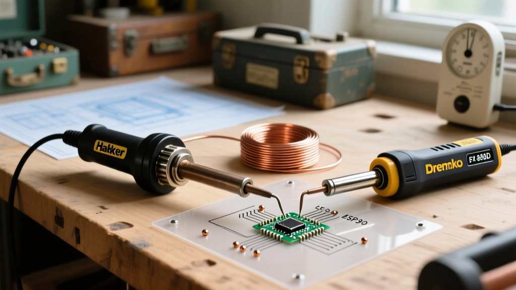
When a high-end soldering station fails, the immediate instinct is often to replace the entire unit. However, as of 2026, premium stations like the Hakko FX-888D (retailing around $115) or the Weller WE1010NA (around $120) are built with modular, user-replaceable components. Performing a DIY soldering iron repair on a failed heating element or a frayed handpiece cord typically costs between $12 and $25 in parts, saving you from discarding a perfectly functional PID controller and power supply.
Before opening your handpiece, it is critical to observe proper electrical safety. While the handpiece operates on low voltage (typically 24V AC or DC), the base station contains mains-voltage capacitors that can retain a lethal charge even when unplugged. Always disconnect the station from the wall and allow a minimum of 15 minutes for capacitor discharge before opening the base unit. For handpiece repairs, ensure the tool is completely cool to avoid severe burns from residual thermal mass in the heating element.
Diagnostic Matrix: Identifying the Point of Failure
Accurate troubleshooting requires isolating the failure to one of three primary subsystems: the tip/cartridge, the composite heating element, or the power delivery cord. Use a digital multimeter (DMM) set to the Ohms (Ω) range to perform continuity and resistance checks.
| Symptom | Probable Root Cause | Diagnostic Test | Repair Action |
|---|---|---|---|
| Station displays 'H-E' or sensor error | Open thermocouple circuit | Measure sensor pins for continuity | Replace tip (T12) or element (A1321) |
| Station powers on, but tip stays cold | Failed heating element or broken cord wire | Measure heater pins for expected resistance | Replace element or re-solder cord joints |
| Erratic temperature readings / wild swings | Intermittent cord connection or oxidized socket | Wiggle cord while monitoring resistance | Replace handpiece cord and clean DIN pins |
| Tip melts solder but recovery time is extremely slow | Thermal barrier (oxidation) or pitted tip plating | Visual inspection of tip surface | Replace tip; do not file or sand |
Deep Dive 1: Integrated Cartridge Tips (T12 / TS100 / Pinecil)
Modern portable and high-end stations increasingly use integrated cartridge tips, such as the T12 standard or the TS-B2 tips used in the TS100 and Pinecil V2. In these designs, the heating element and the thermocouple are wired in series inside the metal shaft of the tip itself. This provides rapid thermal response but means a failed heater requires replacing the entire tip, not just a separate ceramic element.
Testing Integrated Cartridges
To diagnose a Pinecil or TS100 that refuses to heat, remove the tip and locate the two contact pads at the base. Set your multimeter to the lowest Ohms range. A healthy TS-B2 or T12 cartridge will read between 7.5 Ω and 9.0 Ω at room temperature. If your DMM reads 'OL' (Open Loop) or infinite resistance, the internal nichrome wire has snapped, usually due to mechanical shock (dropping the iron) or severe thermal overstress. Because the heater is encased in a sealed ceramic and metal matrix, repair is impossible; you must purchase a replacement cartridge, which typically costs between $3 and $8.
Deep Dive 2: Repairing Composite Heating Elements (Hakko A1321)
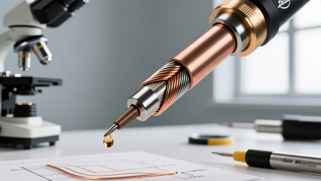
Traditional composite stations, most notably the ubiquitous Hakko FX-888D, separate the heating element from the tip. The Hakko A1321 is a ceramic composite heater that slides into the handpiece and accepts T18 series tips. These elements are highly reliable but can fail if subjected to prolonged dry-heating or physical bending.
The 5-Pin DIN Pinout and Multimeter Testing
The Hakko handpiece connects via a 5-pin DIN connector. To perform soldering iron repair on the element, you must test the correct pins at the base station's receptacle (with the station unplugged and turned on to close internal relays, if applicable, or directly at the handpiece plug):
- Pins 1 & 2 (Heater): A healthy A1321 heater will measure between 50 Ω and 60 Ω. A reading of 'OL' indicates a blown ceramic heater.
- Pins 3 & 4 (Sensor): The internal thermocouple should read very low resistance, typically 1.5 Ω to 3.0 Ω. An open circuit here triggers the base station's safety shutoff.
- Pin 5 (Ground/Shield): This connects to the metal spring inside the handpiece that touches the T18 tip, providing ESD (Electrostatic Discharge) grounding to protect sensitive microcontrollers. Ensure continuity between Pin 5 and the tip itself; resistance should be less than 2 Ω.
If the element tests out of spec, purchase an OEM Hakko A1321 replacement (approx. $14). Avoid $4 aftermarket clones; they frequently use inferior thermocouple wire that causes the PID controller to overshoot target temperatures by 50°C or more, risking severe damage to PCB pads and components.
Deep Dive 3: Handpiece Cord and Strain Relief Failures
According to OSHA guidelines on hand and power tools, flexible cords on electrical tools are highly susceptible to damage from pulling, bending, and environmental heat. In soldering stations, the most common point of failure is the internal solder joint where the silicone wires meet the PCB or terminal block inside the handpiece handle.
Executing a Cord Repair
If your station exhibits intermittent heating or the cord feels stiff and brittle near the strain relief, the internal wires have likely fatigued and snapped. To repair this:
- Unscrew the handpiece handle and carefully slide the bakelite or silicone sleeve back.
- Desolder the existing wires from the terminal block. Note the color coding (typically Red/White for heater, Blue/Yellow for sensor, Green for ground).
- Cut away the damaged section of the cord. If the damage extends deep into the main cable, you must replace the entire cord assembly (approx. $18-$25 for an OEM silicone cord).
- Critical Material Warning: Never use standard PVC-jacketed wire for internal handpiece repairs. The ambient temperature inside the handle can exceed 80°C, and accidental contact with the iron tip will instantly melt PVC, causing a short circuit. You must use 24 AWG or 22 AWG high-flex silicone wire rated for at least 200°C.
- Apply a small dab of high-temperature RTV silicone over the new solder joints to act as a secondary strain relief before reassembling the handle.
Preventative Maintenance: Extending Element and Tip Lifespan
The most effective soldering iron repair is the one you never have to make. Tip and element degradation are largely driven by improper maintenance habits that violate industry standards. The IPC J-STD-001 standard for soldered electrical assemblies emphasizes strict thermal management to prevent damage to both the workpiece and the soldering equipment.
The Wet Sponge vs. Brass Wool Debate
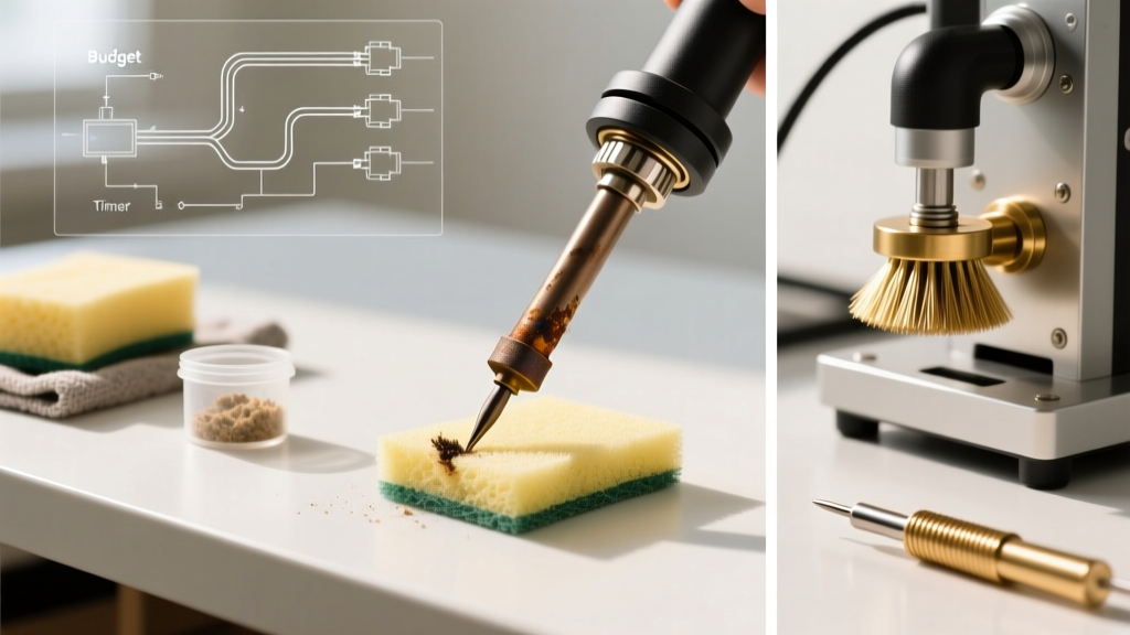
Many hobbyists and legacy technicians still use wet cellulose sponges to clean their tips. This practice induces rapid thermal shock. When a 350°C tip hits a room-temperature wet sponge, the surface temperature plummets by over 150°C in milliseconds. This extreme thermal cycling causes micro-fractures in the tip's iron plating. Once the plating cracks, the underlying copper core is exposed to molten solder and aggressive flux chemistry, leading to rapid pitting and dissolution.
Expert Directive: Discard the wet sponge. Use a dry brass wire sponge (often sold as 'tip cleaner') to remove oxidized solder and carbonized flux. Brass is softer than the iron plating, effectively scrubbing the tip without scratching it or inducing thermal shock. For stubborn flux residue, use a dedicated tip tinner/cleaner chemical paste.
Combating 'Black Tip' Oxidation
Leaving a soldering iron idle at 400°C (a common bad habit when working on complex assemblies) causes the iron plating to oxidize rapidly, turning black and refusing to wet with fresh solder. This is not a failure of the heating element, but a surface chemistry issue. Never attempt to scrape or sand a blackened tip; you will remove the microscopic iron layer and destroy the tip instantly. Instead, lower the temperature to 250°C, apply a generous amount of leaded solder (which contains mild rosin flux), and let it sit for five minutes. The flux will gently reduce the oxidation, allowing you to wipe it clean with brass wool and re-tin with fresh solder.
When to Abandon Repair and Upgrade
While DIY soldering iron repair is highly practical for element and cord replacements, certain failures dictate a full system upgrade. If the base station's TRIAC (the component that switches AC power to the transformer) fails short-circuit, the iron will heat uncontrollably until the tip glows red and melts the handpiece. Furthermore, if the digital PID controller begins displaying erratic, uncalibratable errors despite verified good element resistance, the logic board has likely suffered from flux vapor ingress or capacitor degradation. In these scenarios, replacing a $120 station is safer and more economically viable than attempting component-level board repair. For comprehensive safety protocols regarding equipment ventilation and fume extraction during both use and repair, always consult the CCOHS soldering safety guidelines to ensure your workspace remains compliant and healthy.