
The JBC C210 Ecosystem: Precision Meets Complexity
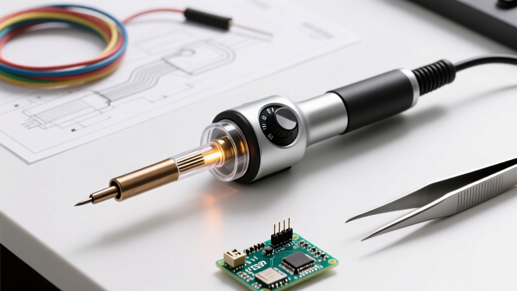
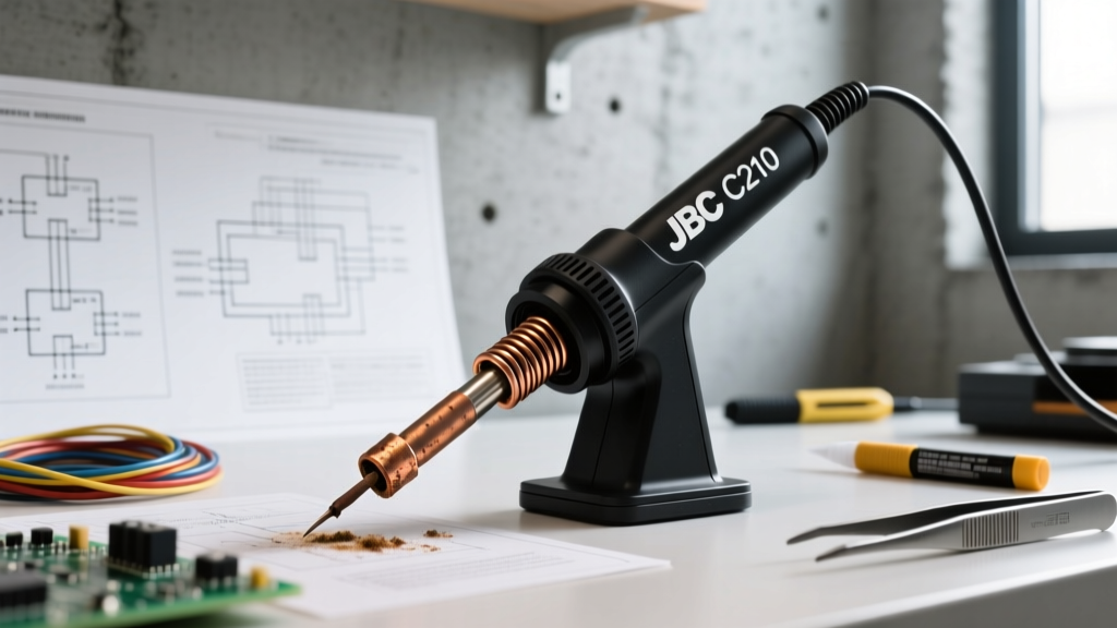
In the realm of micro-soldering and high-density PCB rework, the JBC C210 series remains the undisputed gold standard as of 2026. Designed specifically for the T210 handle, C210 cartridges (such as the ultra-fine C210-105 conical or the C210-114 spoon tip) deliver unmatched thermal recovery for 0201 and 01005 SMD components. However, the miniaturization that makes the JBC C210 soldering iron so effective also makes it highly susceptible to specific failure modes. Unlike larger soldering systems, the C210 integrates the heating element and thermocouple directly into the disposable tip cartridge, shifting the troubleshooting focus from the station to the tip-handle interface.
This comprehensive troubleshooting guide dives deep into the metallurgical, electrical, and mechanical failure points of the C210 system. Whether you are battling rapid tip oxidation, intermittent station errors, or degraded thermal transfer, the following diagnostics will help you isolate the fault without unnecessarily replacing $45 cartridges or $130 handles.
C210 Diagnostic Matrix: Symptoms and Root Causes
Before reaching for a replacement part, cross-reference your system's behavior with this diagnostic matrix. Understanding the exact failure signature is critical for accurate troubleshooting.
| Symptom | Probable Root Cause | Diagnostic Test | Resolution |
|---|---|---|---|
| Station displays 'Error 8' | Open circuit in heater or sensor | Multimeter continuity on tip pins | Replace C210 cartridge or T210 cable |
| Station displays 'Error 9' | Short circuit in tip or handle | Check for solder bridges on handle PCB | Clean handle contacts; replace tip |
| Tip fails to melt solder | Collet wear or internal oxidation | Visual inspection of tip shank | Replace T210 collet (Part #0013865) |
| Rapid tip blackening | Flux carbonization / dry heating | Review sleep mode settings | Chemical tinning; adjust standby temp |
| Erratic temperature readings | Degraded thermocouple junction | Monitor temp graph on CD-2S station | Replace C210 cartridge |
Electrical Diagnostics: Testing the Cartridge and Handle
The JBC C210 cartridge utilizes a proprietary 3-pin internal architecture: Heater Positive, Thermocouple Positive, and a Common Ground. When a JBC CD-2S or CD-2BQF station throws an Error 8 (Open Circuit), it means the station cannot complete the circuit to either the heater or the sensor.
Step-by-Step Multimeter Testing
- Isolate the Tip: Remove the C210 cartridge from the T210 handle. Set your digital multimeter to the lowest Ohms range (typically 200Ω).
- Measure Heater Resistance: Place probes on the two outer pins of the C210 tip base. A healthy C210 heater core should read between 2.5Ω and 3.5Ω at room temperature. A reading of 'OL' (Open Loop) confirms a blown internal heater trace.
- Measure Sensor Resistance: Place probes on the center pin and either outer pin. The thermocouple should read between 1.0Ω and 2.0Ω. An 'OL' reading here indicates a fractured sensor wire, which triggers Error 8 on the station.
- Test the T210 Handle Cable: If the tip tests perfectly, the fault lies in the handle or cable. Probe the 5-pin connector at the cable's station end while the tip is inserted. Flex the silicone cable near the handle strain relief. If resistance fluctuates or spikes, the internal wiring has fatigued—a common failure mode after 2-3 years of heavy bench use.
Expert Insight: Never use the diode test mode on your multimeter when probing JBC cartridges. The test voltage can occasionally trip the internal micro-controller protection circuits in newer active-tip designs, leading to false 'dead tip' diagnoses.
Metallurgical Failures: Tip Oxidation and Plating Degradation
C210 tips are engineered with a high-conductivity copper core encased in an iron plating layer approximately 100 to 150 microns thick. This iron layer is what prevents the molten solder from dissolving the copper. However, in 2026, the widespread use of aggressive lead-free alloys like SAC305 (Sn96.5/Ag3.0/Cu0.5) accelerates iron depletion if proper maintenance is ignored.
The 'Black Tip' Phenomenon
When a C210 tip turns black and refuses to wet, the iron plating has oxidized, forming a barrier that halts thermal transfer. According to IPC J-STD-001 workmanship standards, an oxidized tip must never be scraped with abrasive materials, as this permanently destroys the microscopic iron layer.
Chemical Recovery Protocol
- Step 1: Lower the station temperature to 250°C. High heat accelerates oxidation; attempting to clean a blackened tip at 380°C is futile.
- Step 2: Submerge the tip in a high-activity rosin-based flux (e.g., Kester 186 or Amtech NC-559-V2-TF). The flux will chemically reduce the iron oxide layer.
- Step 3: Apply a generous amount of leaded Sn63/Pb37 solder (18 AWG) directly to the tip while it is submerged in the flux pool. The lead acts as a wetting catalyst, helping to break through the remaining oxidation.
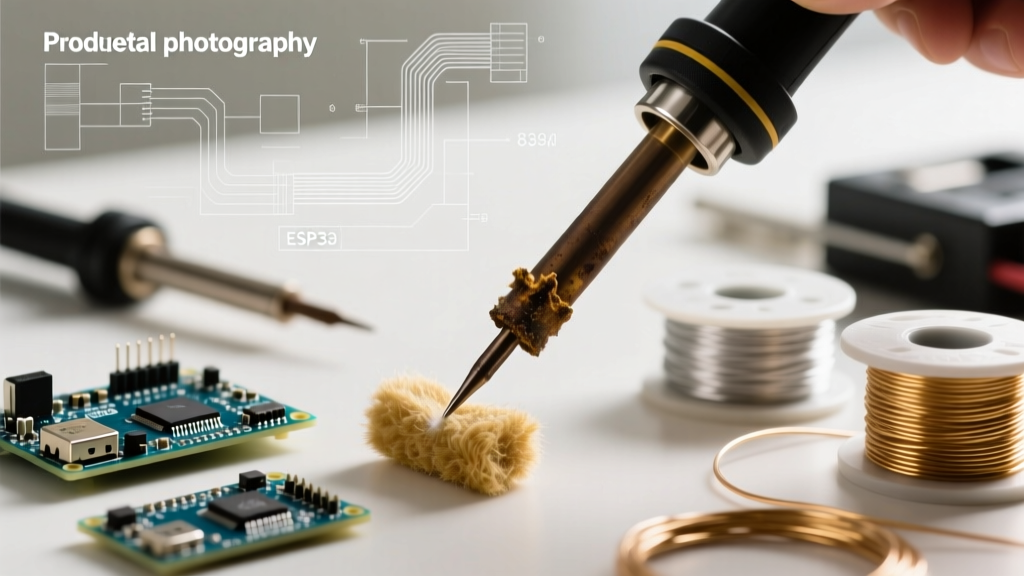
- Step 4: Wipe gently on a damp cellulose sponge (never dry brass wool, which can bend the fragile C210-105 conical shaft). Repeat until the tip shines.
If the tip remains black after three cycles, the iron plating has pitted through to the copper core. The cartridge is structurally compromised and must be discarded to prevent copper contamination on your PCB pads, a critical violation of NASA NEPP soldering reliability standards for aerospace and medical electronics.
Mechanical Maintenance: The T210 Collet and Sleep Sensors
A frequently misdiagnosed issue in the C210 ecosystem is poor thermal transfer despite the station reading the correct temperature. This is almost always a mechanical interface failure at the T210 handle collet.
Collet Wear and Contact Resistance
The T210 handle secures the C210 tip using a precision-machined brass collet. Over thousands of tip swaps, the internal tensioning fingers of the collet fatigue and lose their spring memory. When this happens, the electrical contacts on the tip shank do not mate firmly with the handle's internal pogo pins. This introduces micro-ohms of contact resistance, causing the station to miscalculate the power delivery and resulting in a 'cold' tip.
The Fix: Replace the T210 collet assembly. The OEM JBC part number is 0013865, which retails for approximately $15 to $20. To replace it, simply unscrew the aluminum front nut of the T210 handle, drop in the new collet, and reassemble. This single maintenance step resolves 80% of 'poor heating' complaints and saves users from falsely blaming the station's power supply.
Sleep Mode and Standby Sensor Calibration
The T210 handle features a magnetic reed switch or Hall effect sensor (depending on the exact production year) that detects when the iron is placed in the aluminum stand. If your C210 iron fails to enter sleep mode, or conversely, refuses to wake up, the issue is rarely the station. Instead, check the magnetic ring located inside the silicone grip of the T210 handle. If the handle has been dropped, the internal magnet may have shifted out of alignment with the sensor on the handle's internal PCB. Carefully rolling the magnet back into its designated channel inside the grip housing will restore proper standby functionality.
Summary of Best Practices for 2026
Maintaining a JBC C210 setup requires a shift in mindset from traditional soldering irons. Because the thermal mass is exceptionally low, the system relies entirely on the integrity of the tip-to-handle electrical connection and the microscopic iron plating on the cartridge. By utilizing precise multimeter diagnostics, adhering to chemical tinning protocols over abrasive cleaning, and routinely replacing the $15 T210 collet, you can maximize the lifespan of your C210 consumables and maintain the sub-second thermal recovery required for modern micro-BGA and 01005 passive rework.