
The Core Physics: Solder Alloy Melting Points vs. Iron Temperature
The most common mistake beginners make when asking "how hot should a soldering iron be" is assuming the iron's dial temperature must match the solder's melting point. In reality, your soldering iron tip must be significantly hotter than the alloy's liquidus point to overcome the thermal mass of the PCB pads, component leads, and ambient heat dissipation. However, cranking your station to 450°C (842°F) to "melt it faster" is a catastrophic error that oxidizes tips, lifts copper pads, and carbonizes flux.
As of 2026, modern electronics manufacturing relies heavily on lead-free alloys with higher melting points, making precise thermal management more critical than ever. The ideal temperature is a balancing act between achieving rapid wetting (usually within 2 to 4 seconds per IPC J-STD-001 standards) and preventing thermal damage to sensitive silicon and FR4 fiberglass substrates.
Baseline Temperature Matrix by Solder Alloy
| Solder Alloy | Composition | Melting Point | Recommended Tip Temp | Primary Use Case |
|---|---|---|---|---|
| Sn63/Pb37 | 63% Tin / 37% Lead | 183°C (361°F) | 300°C - 330°C | Prototyping, hobbyist PCBs, vintage repair |
| SAC305 | 96.5% Sn / 3.0% Ag / 0.5% Cu | 217°C - 220°C | 330°C - 360°C | Commercial lead-free PCB assembly |
| Sn96.5/Ag3.0/Cu0.5 | Similar to SAC305 | 221°C (430°F) | 340°C - 370°C | High-reliability automotive/aerospace |
How Hot Should a Soldering Iron Be? (By Application)
Thermal mass dictates temperature. A tiny 0402 surface-mount resistor requires a completely different thermal approach than a 10AWG silicone wire on an XT60 battery connector. Here is how to set your station based on the physical geometry of your joint.
1. Through-Hole PCBs & Standard Wires (24AWG to 14AWG)
For standard through-hole components like DIP ICs, capacitors, and mid-gauge wires, the sweet spot is 320°C to 340°C when using 63/37 leaded solder. If you are using SAC305 lead-free paste or wire, bump this to 350°C. At this range, the flux activates properly, cleaning the oxidation off the copper before the solder flows. As detailed in SparkFun's Through-Hole Soldering Guide, the iron should contact both the pad and the lead simultaneously for 2 seconds before feeding solder.
2. Surface Mount Devices (SMDs) & Fine Pitch
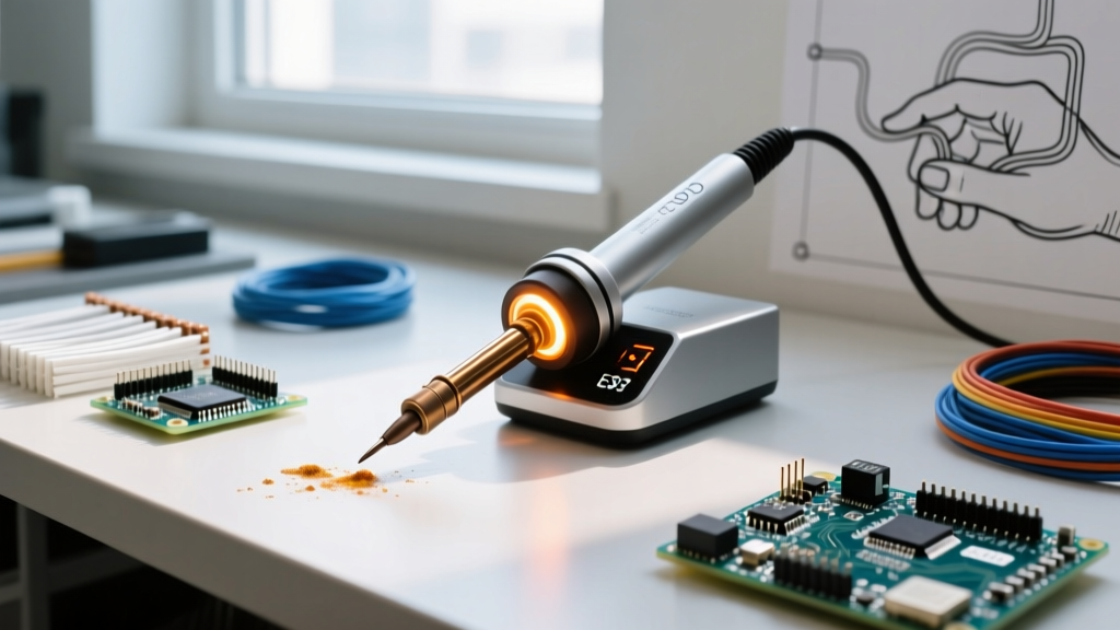
When soldering 0402 or 0603 passives, SOICs, or QFNs, lower temperatures are mandatory. Set your iron to 300°C - 320°C (for leaded) or 330°C - 340°C (for lead-free). SMD pads have minimal thermal mass and are highly susceptible to tombstoning (where one side of the component lifts due to uneven surface tension) and pad delamination. Use a micro-pencil or small hoof tip to concentrate the heat precisely without bleeding into adjacent 0.5mm pitch traces.
3. High Thermal Mass: Ground Planes & Heavy Wires (10AWG+)
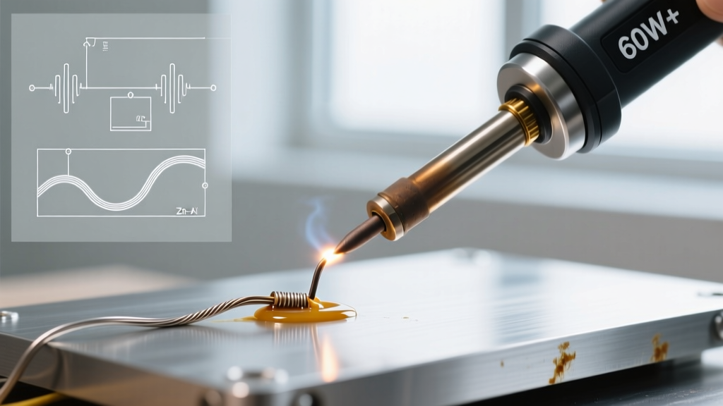
Soldering thick wires to large connectors or multi-layer PCB ground planes is where most hobbyists fail. They see the solder ball up and refuse to flow, so they raise the station to 400°C+. This is the wrong solution. The correct answer is to increase the thermal mass of the tip, not just the temperature. Set your station to 360°C - 380°C, but swap to a massive chisel tip (like the Hakko T18-D52 or JBC C245-945). The physical volume of copper in the tip stores the joules of heat energy required to overcome the heat-sinking effect of a heavy ground plane.
The Danger Zone: Thermal Damage and Flux Carbonization
Exceeding 380°C (716°F) triggers a cascade of chemical and physical failures in your solder joint:
- Flux Carbonization: Rosin-based (RMA) and no-clean fluxes activate between 180°C and 220°C. Above 380°C, the flux burns into a hard, black, non-conductive carbon shell. This prevents the solder from wetting the joint, resulting in a cold, grainy connection that looks like a charred mess.
- Tip Oxidation: At extreme heat, the iron plating on your tip reacts with oxygen and the molten solder, creating a crusty black layer of iron oxide. Once oxidized, the tip will not accept solder, effectively ruining a $15-$40 replacement cartridge.
- FR4 Delamination: Standard FR4 PCB material has a Glass Transition Temperature (Tg) of around 130°C to 170°C. While it can survive brief spikes to 260°C during wave soldering, holding a 420°C iron on a pad for 10 seconds will cause the internal resin to boil and delaminate, permanently destroying the board.
Expert Rule of Thumb: If your solder joint takes longer than 4 seconds to flow, do not increase the temperature. Increase the physical size of your soldering tip or apply a small amount of fresh 63/37 solder to the tip first to create a thermal bridge between the iron and the joint.
Station Architecture: Why Tip Design Dictates Temperature
Not all soldering stations deliver heat equally. The architecture of your heater determines how hot you actually need to set the dial:
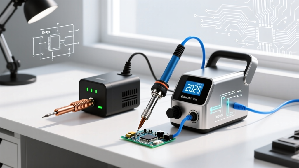
- Ceramic Heater (e.g., Weller WE1010NA, ~$115): The heater is separate from the tip, transferring heat through an air gap or metal sleeve. These suffer from thermal lag. You often need to set the dial 20°C higher than your target to compensate for the temperature drop when the tip touches a cold pad.
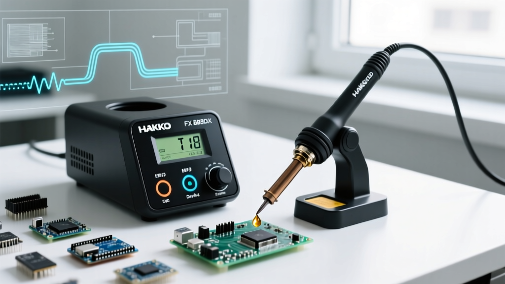
- Composite Heater (e.g., Hakko FX-951, ~$330): The heater is embedded directly into the tip sleeve. Excellent thermal recovery allows you to run the station at a conservative 330°C for most daily tasks without stalling on larger joints.
- Cartridge System (e.g., JBC CD-2BE, ~$550+): The heating element is integrated directly inside the tip, millimeters from the contact point. JBC stations recover in under 1 second. Because there is virtually zero thermal lag, you can run a JBC station 20°C to 30°C cooler than a standard station and achieve the exact same joint quality with less thermal stress on the component.
Expert Workflow: Dialing in Your Temperature Profile
Follow this step-by-step calibration workflow when starting a new project to ensure optimal thermal transfer:
- Identify the Alloy and Mass: Check your solder wire label and assess the largest component you will be attaching.
- Set the Baseline: Set your station to 320°C (for 63/37) or 350°C (for SAC305).
- Tin the Tip: Melt a generous blob of solder onto the tip. If it turns dull or crusty within 5 seconds, your temperature is too high. Drop it by 10°C.
- Test on a Scrap Pad: Apply the tinned tip to a scrap PCB pad and feed wire. Count the seconds until the solder flashes and wicks perfectly.
- Evaluate the Timing: If it flows in 2-3 seconds, your temperature and tip geometry are perfect. If it takes 5+ seconds, swap to a wider chisel tip before touching the temperature dial.
Summary Quick-Reference Matrix
| Task | Alloy | Target Temp | Recommended Tip Shape |
|---|---|---|---|
| 0402 / 0603 SMDs | Sn63/Pb37 | 300°C - 310°C | Micro-Pencil / Fine Conical |
| Standard DIP / SOIC ICs | Sn63/Pb37 | 320°C - 330°C | Small Chisel (1.5mm - 2.5mm) |
| 18AWG - 14AWG Wire | Sn63/Pb37 | 340°C - 350°C | Medium Chisel / Hoof |
| Lead-Free PCB Assembly | SAC305 | 340°C - 360°C | Chisel (matching pad width) |
| XT60 / Heavy Ground Planes | Sn63/Pb37 | 360°C - 380°C | Massive Chisel (5mm+) |
Mastering exactly how hot a soldering iron should be is less about memorizing a single number and more about understanding the relationship between alloy chemistry, thermal mass, and tip geometry. By respecting the activation temperatures of your flux and the thermal limits of your PCB substrates, you will produce shiny, reliable, IPC-compliant joints every time.