
Upgrading or swapping out your soldering iron replacement tips is one of the most cost-effective ways to improve your workflow, but simply sliding a new tip onto the heating element is only half the battle. According to the stringent requirements of IPC J-STD-001 for soldered electrical and electronic assemblies, thermal recovery and precise temperature control at the solder joint are mandatory for reliable intermetallic bond formation. If your replacement tip is improperly seated or uncalibrated, you risk cold solder joints, lifted pads, and premature tip oxidation.
This comprehensive setup and calibration tutorial will walk you through the physics of tip installation, exact seating procedures for the most popular 2026 soldering stations, and the step-by-step calibration process required to synchronize your station’s display with the actual tip temperature.
The Physics of Tip Installation: Why the Air Gap Matters
The core of a high-quality soldering iron replacement tip is oxygen-free copper, chosen for its exceptional thermal conductivity of approximately 385 W/(m·K). In stark contrast, stagnant air has a thermal conductivity of just 0.024 W/(m·K).
If your tip is not fully seated against the ceramic or nichrome heating element, even a microscopic 0.5mm air gap will act as a severe thermal insulator. This forces the station's sensor to overcompensate, leading to massive temperature overshoots and rapid degradation of the tip's iron plating.
Proper installation eliminates this air gap, ensuring the thermocouple reads the true thermal mass of the tip and allowing the PID controller to regulate power delivery accurately.
Step-by-Step Installation Guide for Top Stations
Different manufacturers utilize distinct mechanical retention systems. Here is how to properly install the most common soldering iron replacement tips on the market.
1. Hakko FX-888D and T18 Series Tips
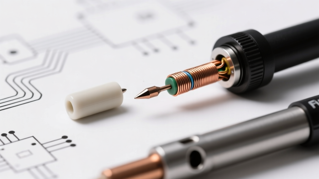
The Hakko T18 series (such as the popular T18-D24 chisel or T18-BC2 bevel) slides over a fragile ceramic heating element.
- Preparation: Ensure the station is unplugged and completely cool. Inspect the ceramic heater for micro-fractures or carbon buildup. Wipe it gently with isopropyl alcohol (IPA) if dirty.
- Insertion: Slide the T18 tip onto the heater. Do not twist or force it. It should slide down until it gently bottoms out against the sensor collar.
- Securing: Thread the enclosure nut back onto the wand. Critical Warning: Hand-tighten the nut, then use the provided wrench to turn it exactly 1/8th of a rotation further. Over-tightening will crack the ceramic heater, resulting in an open-circuit error and a $25 replacement cost for the wand assembly.
2. Weller WE1010 and ETA/RT Series Tips
Weller’s ETA series (for the WE1010) and the premium RT series (for the WT1) use a threaded barrel and sleeve system.
- Alignment: Insert the tip into the heating element sleeve. Ensure the retaining collar is threaded completely onto the wand barrel before insertion.
- Seating: Push the tip firmly inward to compress the internal spring slightly, ensuring the thermocouple makes direct contact with the tip's internal cavity.
- Locking: Thread the retaining collar clockwise. Tighten it firmly by hand, then use the Weller locking wrench to secure it. Do not use pliers, as crushing the collar will warp the sleeve and make future soldering iron replacement tips impossible to remove.
3. Pine64 Pinecil V2 and TS100 Tips
Direct-DC driven irons like the Pinecil V2 use a set-screw (grub screw) retention method for tips like the TS-B2 or TS-C4.
- Orientation: Look closely at the base of the replacement tip. You will see a small, machined flat spot.
- Insertion: Loosen the M2 grub screw on the wand just enough to allow the tip to slide in. Align the flat spot of the tip directly under the grub screw.
- Torque: Tighten the screw using a 1.5mm hex driver. Apply approximately 0.2 Nm of torque. If the screw is not perfectly on the flat spot, it will pinch the internal thermocouple wires, causing an immediate 'Sensor Error' on the OLED screen.
Calibrating Your Station to the New Tip
Every soldering iron replacement tip has a slightly different thermal mass and thermocouple tolerance. According to NASA Workmanship Standard 8739.3 for soldering, equipment must be verified against a known standard to ensure joint reliability. To do this, you need a K-type tip thermometer (such as the Hakko FG-100B, retailing around $180, or the Weller WSDCB).
Calibrating the Hakko FX-888D
- Turn the station OFF.
- Press and hold the UP arrow button while turning the power ON.
- The display will show a password prompt. Enter the default password: 000.
- Navigate to the Sensor Offset menu.
- Set the station to 350°C (662°F) and allow it to stabilize for 3 minutes.
- Place the sensor pad of your tip thermometer on the flat surface of the tinned tip, using a small dab of thermal paste or liquid flux to ensure heat transfer.
- Compare the thermometer reading to the station display. Use the UP/DOWN arrows to adjust the station's offset until the display exactly matches the external thermometer.
- Hold the ENTER button to save and exit.
Calibrating the Pine64 Pinecil V2
The Pinecil V2 handles calibration digitally via its open-source IronOS firmware, as detailed in the official Pine64 Pinecil Wiki.
- Power on the Pinecil and enter the settings menu by pressing the rear button.
- Navigate to Advanced Settings > Calibration.
- Follow the on-screen prompts. The system will ask you to input the current ambient room temperature (use a separate room thermometer for accuracy).
- For tip-specific offset, navigate to Tip Settings > Calibrate Tip. The device will run a resistance check on the thermocouple and automatically calculate the PID tuning parameters for that specific soldering iron replacement tip.
The 3-Second Tinning Rule for Longevity
The moment you install and heat a new tip, the bare iron plating is exposed to atmospheric oxygen. If you do not apply solder immediately, microscopic oxidation begins within seconds, creating a black crust that repels molten solder.
The Setup Protocol:
- For 63/37 Leaded Solder (183°C melt): Set your calibrated station to 250°C. Have your flux-core solder wire ready to touch the tip the exact second it reaches 185°C.
- For SAC305 Lead-Free Solder (217°C melt): Set the station to 320°C. Lead-free alloys require higher thermal mass to wet properly. Apply the solder immediately upon reaching 220°C.
Coat the entire working surface of the tip, including the very apex, creating a protective barrier of tin and flux residue.
Troubleshooting Thermal Lag and Sensor Errors
Even with perfect installation, environmental factors and wear can cause issues. Use this diagnostic matrix to troubleshoot your setup.
| Symptom | Root Cause | Corrective Action |
|---|---|---|
| Tip turns black and solder balls up | Severe oxidation due to dry heating or excessive temperature (>400°C). | Turn off, let cool. Use a brass wire sponge and specialized tip tinner (e.g., Hakko FS-100) to chemically reduce the oxide layer. Re-tin immediately. |
| Station displays 'Sensor Error' or 'Open Circuit' | Thermocouple wire pinched or broken; tip not fully seated. | Power down. Remove tip. Inspect the internal wires for crimps. Re-seat the tip ensuring no lateral stress on the sensor wires. |
| Solder melts slowly despite high display temp | Thermal air gap between heater and tip; heavy oxidation on the heater shaft. | Remove tip. Clean the ceramic heater shaft with a fiberglass scratch pen or IPA. Reinstall, ensuring the tip bottoms out completely. |
| Station overshoots target temp by >20°C | PID controller tuned for a different tip mass; uncalibrated offset. | Perform a full sensor offset calibration using a K-type tip thermometer as outlined in the previous section. |
Final Thoughts on Tip Maintenance
Treating your soldering iron replacement tips as precision thermal instruments rather than disposable consumables will drastically reduce your operating costs and improve your solder joint reliability. Always store your iron with a generous blob of solder on the tip, never use abrasive sandpaper or files on iron-plated tips, and recalibrate your station every time you switch between drastically different tip geometries (e.g., swapping from a micro TS-A conical to a massive TS-K knife tip). By mastering the setup and calibration process, you ensure your equipment performs to the exacting standards required for modern, high-density PCB assembly.