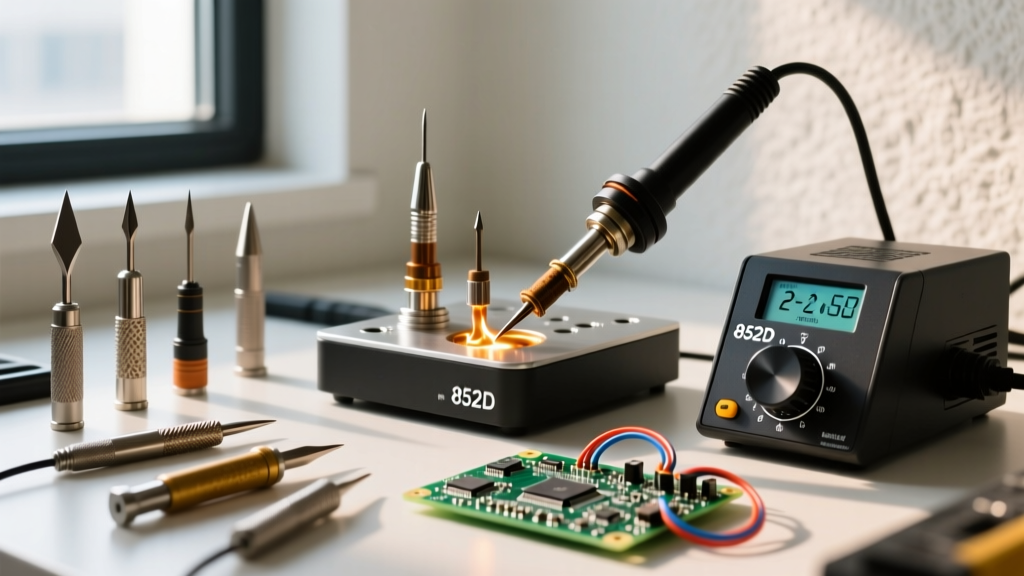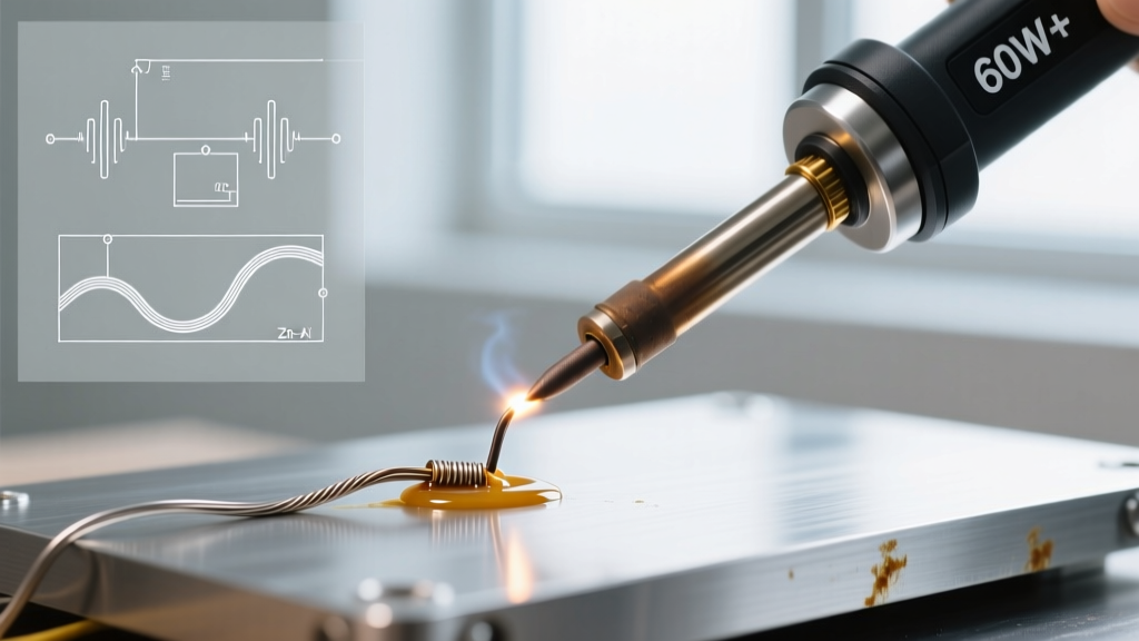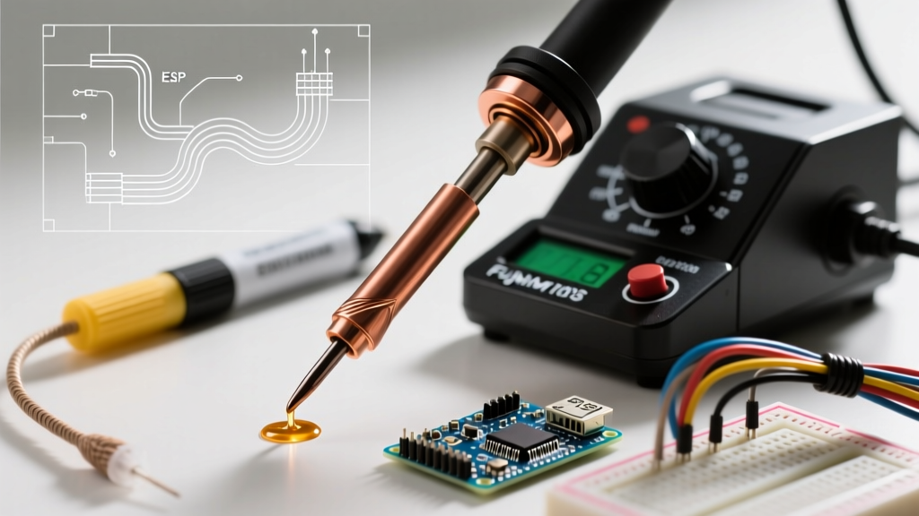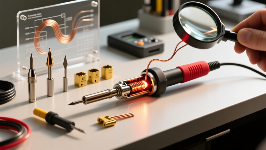

The Reality of DIY Soldering Irons: Safety and Scope
Learning how to build a soldering iron is a classic rite of passage for electronics enthusiasts. It demystifies thermal dynamics, electrical resistance, and material science. However, as we navigate the maker landscape in 2026, safety must dictate our approach. Many outdated tutorials suggest wiring a resistive coil directly to 120V or 240V AC mains. Do not do this. Mains-voltage DIY heating elements lack proper isolation, grounding, and thermal fusing, making them a leading cause of workshop fires and fatal electrocution.
CRITICAL SAFETY WARNING: According to the National Fire Protection Association (NFPA), improper handling of mains voltage and unshielded heating elements are primary catalysts for electrical fires. This guide strictly utilizes a safe, isolated 12V DC architecture. Never connect DIY Nichrome coils directly to wall power.
This beginner guide covers two distinct paths: the educational 12V DC Nichrome Wire Build (to understand the raw physics of resistive heating) and the Modern USB-C Cartridge Build (for a practical, daily-driver tool).
Method 1: The 12V DC Nichrome Wire Iron (Educational Build)
This build creates a functional, low-voltage soldering iron capable of reaching 300°C (572°F), suitable for through-hole components and basic wire tinning. It relies on a benchtop power supply, eliminating any shock hazard.
Bill of Materials & Cost Breakdown
| Component | Specification | Est. Cost (2026) |
|---|---|---|
| Heating Wire | Nichrome 80, 24 AWG (0.51mm) | $12.00 / spool |
| Soldering Tip | 10 AWG Solid Copper Wire (bare) | $4.50 |
| Core / Insulation | Fiberglass Sleeving (6mm ID) | $6.00 |
| Power Source | 12V 5A DC Bench Power Supply | $25.00 |
| Connectors | Ceramic Terminal Block (2-pin) | $2.00 |
| Handle | High-Temp Silicone Tubing or Wood | $5.00 |
Total Build Cost: ~$54.50 (assuming you already own basic wire strippers and pliers).
The Physics: Calculating Your Heating Element
To melt standard 63/37 Sn/Pb eutectic solder (melting point 183°C) or SAC305 lead-free solder (217°C), your tip must transfer enough thermal energy to overcome the heat sink effect of the component leads. We will target 40 Watts of power at 12 Volts DC.
Using Ohm's Law and the Power Equation, we calculate the required resistance:
- Current (I): P / V = 40W / 12V = 3.33 Amps
- Target Resistance (R): V / I = 12V / 3.33A = 3.6 Ohms
Nichrome 80 wire at 24 AWG has a room-temperature resistance of approximately 0.522 Ohms per foot. However, Nichrome exhibits a slight Positive Temperature Coefficient (PTC); resistance increases as it heats up. To account for this, we target a cold resistance of roughly 3.2 Ohms.
Wire Length Required: 3.2 Ohms / 0.522 Ohms/ft = 6.12 feet (approx. 73.5 inches).
Step-by-Step Assembly
- Prepare the Tip: Cut a 4-inch length of 10 AWG solid copper wire. Strip 1 inch of insulation from one end. This bare copper will act as your heat transfer tip. Copper is an excellent thermal conductor, but be aware: bare copper dissolves into molten solder (leaching). Your DIY tip will pit and degrade after roughly 15-20 hours of use, requiring you to snip the end and re-strip it.
- Prepare the Core: Cut a 3-inch piece of 6mm fiberglass sleeving. Slide it over the insulated portion of your copper wire, leaving the 1-inch bare tip exposed.
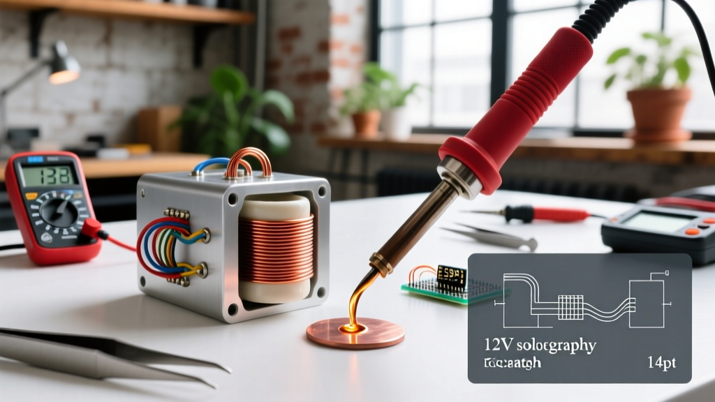
- Wind the Coil: Tightly wrap the 73.5 inches of 24 AWG Nichrome wire around the fiberglass sleeving. Ensure the wraps are touching but never overlapping, as overlapping will create a short circuit and cause the wire to snap from localized overheating.
- Secure the Element: Slide a secondary, slightly larger piece of fiberglass sleeving over the wound Nichrome coil to lock it in place and provide electrical insulation.
- Wire the Connections: Connect the two ends of the Nichrome coil to your ceramic terminal block. Run standard 18 AWG silicone wire from the terminal block to your 12V DC power supply.
- Add the Handle: Slide high-temperature silicone tubing over the fiberglass and terminal block to create a grippable, thermally isolated handle.
Method 2: The Modern 2026 Approach (USB-C Cartridge Build)
While the Nichrome build is an incredible physics lesson, it lacks active temperature control. If you leave it on, it will eventually oxidize and fail. In 2026, the most practical way to build a custom, high-performance soldering iron is to integrate a commercial replacement heating cartridge with a USB-C Power Delivery (PD) trigger board.
By purchasing a replacement T12 or TS101 soldering cartridge (which contains both the heater and the thermocouple in a single package) and wiring it to a custom 3D-printed handle housing a USB-C PD 20V decoy board, you can build an iron that rivals $200 commercial stations for under $35.
Comparison Matrix: Nichrome DIY vs. USB-C Cartridge DIY
| Feature | 12V Nichrome Wire Build | USB-C PD Cartridge Build |
|---|---|---|
| Primary Purpose | Education & Physics Demonstration | Daily Professional / Hobbyist Use |
| Temperature Control | None (Fixed Wattage Output) | Active PID via Microcontroller |
| Heat-up Time | 45 - 60 Seconds | 3 - 5 Seconds |
| Tip Longevity | Low (Copper Leaching) | High (Iron-Plated Copper) |
| Power Source | 12V 5A Bench Supply | Any 65W+ USB-C PD Wall Charger |
Thermal Recovery and IPC Standards
When building your own iron, you must understand thermal recovery. According to the IPC J-STD-001 standards for soldered electrical assemblies, a proper solder joint requires the pad and lead to reach the solder's liquidus temperature simultaneously to ensure proper wetting and intermetallic compound (IMC) formation.
A DIY Nichrome iron has a high thermal mass but slow recovery. If you touch it to a large ground plane on a printed circuit board, the copper plane will act as a massive heat sink, dropping the tip temperature below 183°C. The result is a 'cold solder joint'—a dull, grainy connection with high electrical resistance and mechanical fragility. To mitigate this with a DIY iron, you must use a thicker copper tip (like 8 AWG) to increase thermal mass, though this increases the time required to initially heat the tool.
Troubleshooting Common DIY Iron Failures
- Failure Mode: Nichrome Wire Snaps After a Few Uses
Cause: Grain growth due to overheating. If your coil glows bright orange (exceeding 900°C), the metallurgical structure of the Nichrome breaks down, becoming brittle.
Fix: Increase the length of your wire slightly to raise the resistance, thereby lowering the total wattage and peak temperature. - Failure Mode: Solder Refuses to Stick to the Copper Tip
Cause: Copper oxidation. Bare copper oxidizes rapidly at 300°C, creating a black barrier that solder will not wet.
Fix: You must 'tin' the DIY tip immediately upon heating. Melt a small amount of rosin-core solder onto the tip the second it reaches melting temperature to create a protective metallic layer. - Failure Mode: Power Supply Shuts Down Immediately
Cause: Cold inrush current. As noted, cold Nichrome has lower resistance. When you first apply 12V, the current spike may exceed your power supply's 5A overcurrent protection limit.
Fix: Use a power supply with a 'constant current' (CC) mode or a soft-start circuit, or add a 0.5 Ohm power resistor in series to limit the initial inrush current.
Building your own soldering iron bridges the gap between abstract electrical theory and tangible workshop skills. Whether you choose the raw educational value of the 12V Nichrome coil or the modern utility of a USB-C PD cartridge build, you now possess the engineering data to execute the project safely and effectively.