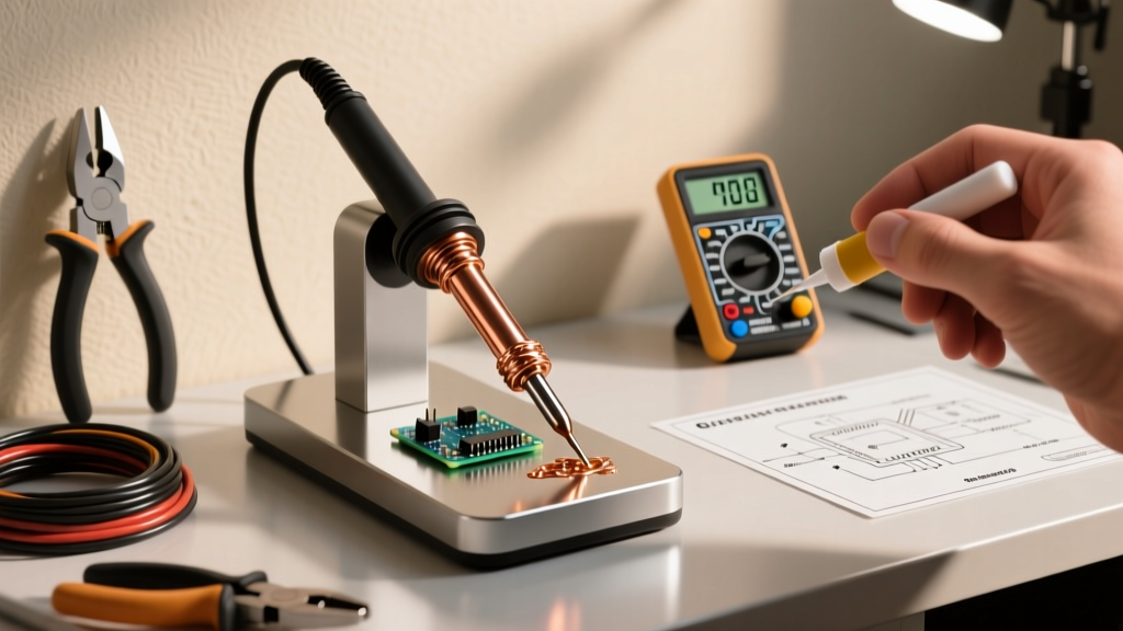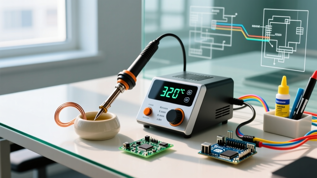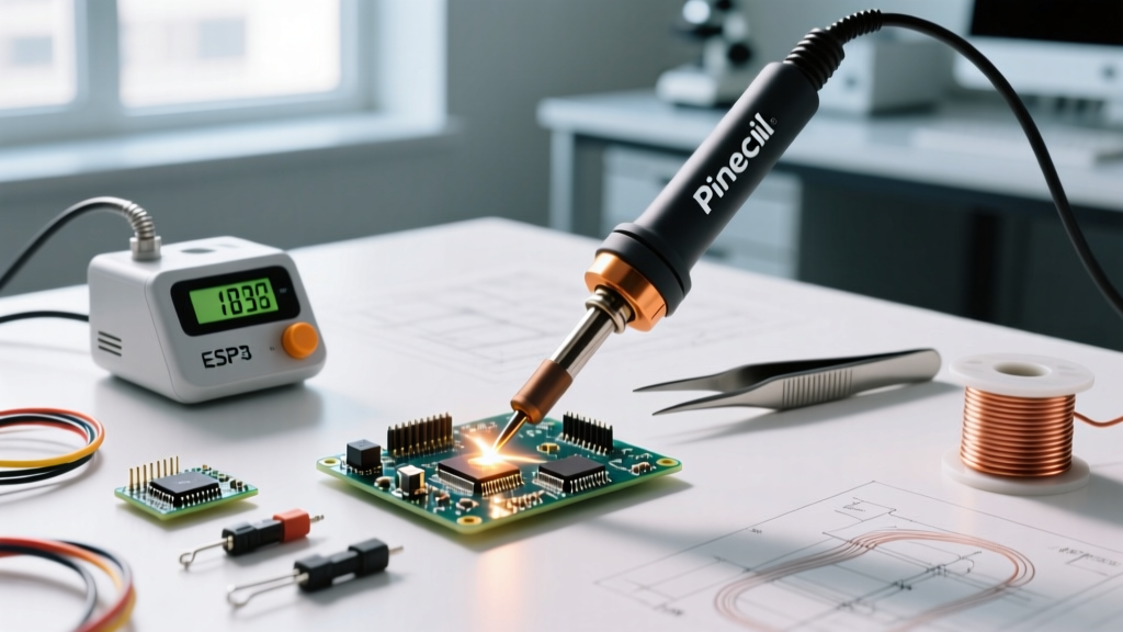

Hardware Preparation and Tip Seating
The Pine64 Pinecil V2 represents a massive leap in portable soldering technology, leveraging a Bouffalo Lab BL706 RISC-V microcontroller to deliver rapid thermal recovery and precise temperature control. However, out of the box, the pinecil portable soldering iron requires careful hardware preparation to ensure optimal thermal transfer and prevent damage to the internal ceramic heater.
Proper Tip Insertion Technique
The most common point of failure for new Pinecil users is improper tip seating. The heater core relies on direct physical contact with the inner copper wall of the soldering tip.
- Align the Set Screw: Locate the set screw on the front of the metal collar. Do not fully unscrew it; simply loosen it enough to allow the tip to slide in.
- Seat the Tip Firmly: Push the tip all the way back until it physically bottoms out against the ceramic heating element. You should feel a slight resistance.
- Apply Precise Torque: Using the included hex key, tighten the set screw until it is snug against the tip's flat recess, then add exactly one-eighth of a turn. Overtightening will strip the soft aluminum threads or snap the screw, while undertightening causes intermittent 'TIP' errors due to poor electrical contact.
Expert Warning: Never hot-swap tips on the Pinecil V2. Always power down and allow the unit to cool below 50°C before loosening the set screw. The thermal expansion of the metal collar can cause the screw to bind, leading to stripped threads.
Power Supply Selection and Handshake Protocols
The Pinecil V2 supports dual power input paths: a USB-C port and a 5.5x2.5mm DC barrel jack. Your choice of power supply dictates the iron's maximum wattage and heat-up time.
| Power Source | Protocol / Spec | Max Wattage | Heat-Up Time (to 320°C) |
|---|---|---|---|
| USB-C (PD 3.0/3.1) | 20V @ 3.25A (65W Charger) | 65W | ~14 seconds |
| USB-C (QC 3.0) | 12V / 9V Negotiation | 24W - 36W | ~28 seconds |
| DC Barrel Jack | 24V DC (5.5x2.5mm) | 120W | ~6 seconds |
For heavy ground-plane soldering or large gauge wires, a 24V DC power supply is mandatory to unlock the full 120W thermal recovery curve. For standard SMD and through-hole PCB work, a 65W USB-C PD GaN charger provides the best balance of portability and performance. According to the official Pine64 Wiki, the V2 model features an upgraded USB-C PD negotiation chip that resolves the 'handshake timeout' issues present in the original V1 hardware.
Flashing and Updating IronOS Firmware
The stock firmware is functional, but updating to the latest community-maintained IronOS is critical for accessing advanced PID tuning, custom boot animations, and improved USB-C PD stability.
Step-by-Step Drag-and-Drop Update (V2 Only)
- Download the latest
Pinecilv2_EN.bin(or multi-language equivalent) from the IronOS GitHub releases page. - Ensure the Pinecil is completely powered off and disconnected from any power source.
- Press and hold the B button (the button closest to the tip).
- While holding the B button, connect the USB-C port to your computer using a data-capable USB-C cable.
- The Pinecil will mount as a mass storage device named
IRONOSorDFU. - Drag and drop the
.binfile into the root directory of the mounted drive. - Once the file transfer completes, safely eject the drive and unplug the USB cable. The firmware is now flashed.
Thermocouple Calibration Procedure
Out of the box, the Pinecil's internal ADC (Analog-to-Digital Converter) offset may not perfectly match the specific resistance curve of your installed tip. Furthermore, the Cold Junction Compensation (CJC) sensor, which is integrated directly into the RISC-V silicon, requires environmental baselining. Calibration is mandatory if you swap between different tip brands (e.g., genuine ST-B2 vs. third-party TS100 clones) or if your solder refuses to melt despite the screen reading 350°C.
Executing the Auto-Calibration Routine
- Establish Room Temperature Baseline: Ensure the iron has been sitting unplugged in your workspace for at least 20 minutes. The internal chip temperature must match the ambient room temperature for the CJC sensor to calibrate correctly.
- Access the Menu: Power on the iron. From the main soldering screen, do a long press on the B button to enter the settings menu.
- Navigate to Calibration: Scroll through the menu using the A button until you reach
Advanced settings(indicated by a gear or wrench icon, depending on your UI theme). SelectCalibrate temperature. - Run the Diagnostic: Press the A button to start. The screen will prompt you to confirm. The iron will begin heating the tip to a specific threshold while measuring the thermocouple's voltage delta.
- Completion: Once the cycle finishes, the iron will save the new ADC gain and offset values to the EEPROM. Power cycle the device to apply the changes.
For professional electronics assembly conforming to IPC J-STD-001 thermal profiling standards, you should verify this calibration using a tip thermocouple tester placed directly on the bevel of the iron to ensure the displayed temperature matches the physical surface temperature within ±2°C.
PID Tuning and Power Limits
IronOS allows granular control over the PID (Proportional-Integral-Derivative) controller. If you notice the temperature overshooting your target by 10°C or more before settling, or if it oscillates during heavy thermal loads, adjusting the Power Limit and PID settings is required.
- Power Limit (Watts): If using a 65W USB-C charger, set the software power limit to 60W. This leaves a 5W buffer for the screen, microcontroller, and PD negotiation overhead, preventing the charger from tripping its over-current protection and resetting the iron mid-solder.
- Sleep Sensitivity: The Pinecil V2 uses an internal accelerometer to detect motion. If you are working on a heavy, vibrating workbench (e.g., near a CNC mill or heavy machinery), increase the
Sleep Sensitivitythreshold to prevent the iron from falsely entering sleep mode while resting in its stand. - Boost Mode: Configure the 'Boost' temperature to 400°C and map it to a long-press of the A button. This provides a temporary thermal surge for desoldering large ground pads without permanently altering your base profile.
Troubleshooting Common Setup Errors
Even with meticulous setup, the RISC-V architecture can throw specific error codes that require immediate attention.
The 'CJ' Error (Cold Junction Failure)
This indicates the internal CJC sensor is reading an impossible ambient temperature (e.g., -40°C or +85°C). This usually happens if you calibrate the iron immediately after it has been running, or if the internal flex cable is slightly unseated. Fix: Let the iron cool to room temperature, reboot, and recalibrate. If it persists, open the metal collar and ensure the internal ribbon cable is fully seated on the PCB.
The 'TIP' Error (Open Circuit)
The microcontroller cannot detect the thermocouple or heater coil. Fix: 90% of the time, this is caused by an undertightened set screw or oxidation on the tip's contact rings. Remove the tip, clean the contact rings with isopropyl alcohol and a fiberglass scratch pen, reseat it firmly, and retighten the set screw.
USB-C PD Negotiation Loop
If the screen flashes the voltage and repeatedly clicks without heating, the power supply is failing the PD handshake. Fix: Use a high-quality, 100W-rated USB-C cable with E-Marker chips. Cheap, phone-charging cables lack the necessary data lines to negotiate the 20V/3A profile required by the Pinecil.