
Beyond the Dictionary: How Engineers Define a Soldering Iron
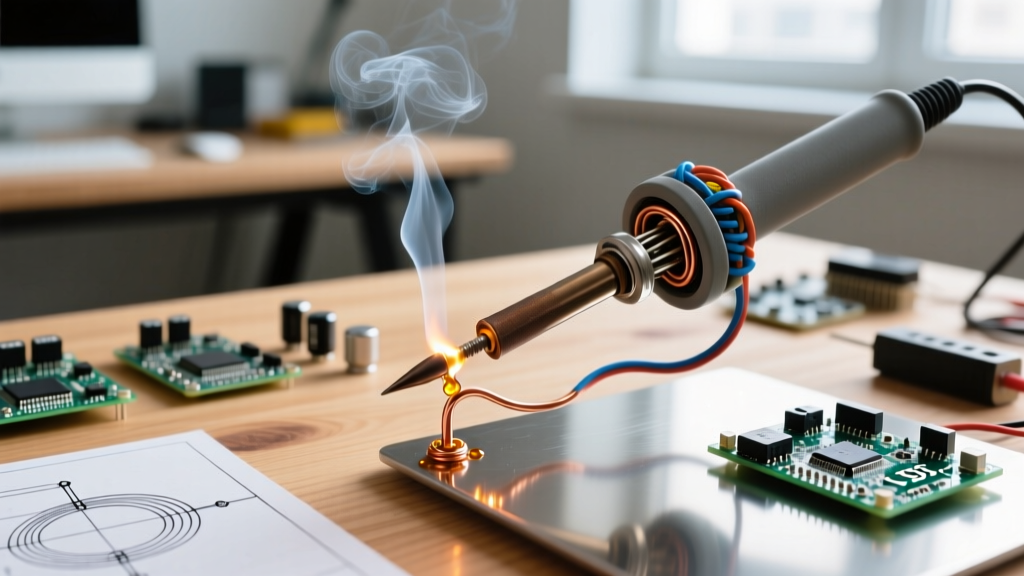
To simply define a soldering iron as a 'hand tool used to melt solder' is a vast oversimplification that ignores the complex thermodynamics, metallurgy, and closed-loop control systems inherent in modern electronics assembly. As we navigate the electronics landscape of 2026, the industry-wide transition to lead-free alloys like SAC305 (Sn96.5/Ag3.0/Cu0.5) has fundamentally shifted how engineers and technicians define, select, and operate these tools. Lead-free solder requires liquidus temperatures around 217°C to 220°C, demanding higher thermal recovery rates and more sophisticated tip architectures than the legacy 63/37 tin-lead eutectic alloys of the past.
This feature deep dive moves beyond the basic dictionary definition to explore the true engineering anatomy, thermal dynamics, and control algorithms that define a professional-grade soldering iron today. Whether you are repairing multilayer PCBs or assembling high-reliability aerospace components, understanding these variables is the difference between a robust metallurgical bond and a catastrophic field failure.
The Metallurgical Anatomy of a Soldering Tip
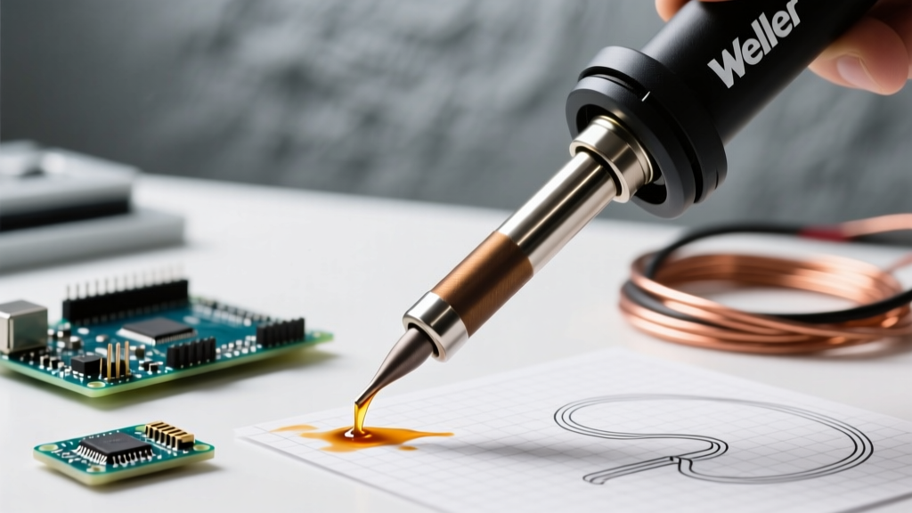
When experts define a soldering iron's performance, they are largely defining the architecture of its tip. A modern high-performance tip is not a single piece of metal; it is a complex, multi-layered metallurgical sandwich designed to balance thermal conductivity with corrosion resistance.
The Copper Core
The heart of any quality tip is an oxygen-free high thermal conductivity (OFHC) copper core. Copper boasts a thermal conductivity of approximately 385 W/m·K, allowing it to rapidly pull heat from the internal heating element and push it toward the solder joint. However, copper dissolves rapidly into molten solder—a destructive phenomenon known as leaching or dissolution.
The Iron Plating
To prevent the copper core from dissolving, manufacturers electroplate a layer of pure iron over the working end. Iron has a much lower thermal conductivity (roughly 80 W/m·K) but is highly resistant to solder leaching. The thickness of this iron plating—typically ranging from 0.08mm on high-precision micro-tips to 0.8mm on heavy-duty chisel tips—directly defines the tool's thermal bottleneck and operational lifespan.
Chromium and Tin Layers
Above the iron plating, a microscopic layer of chromium is applied to the non-working surfaces to prevent solder from wetting and creeping up the shaft. Finally, the working end is pre-tinned with a layer of solder to prevent oxidation during storage and ensure immediate thermal transfer upon first use.
Defining Thermal Dynamics: Wattage vs. Thermal Mass
A common mistake among beginners is to define a soldering iron's power strictly by its wattage. In reality, wattage (the rate of energy transfer) is only half the equation; thermal mass (the ability to store heat energy in Joules) is equally critical when defining how the tool performs on a workbench.
| Tip Geometry | Thermal Mass | Typical Heater Wattage | Ideal Application |
|---|---|---|---|
| Micro Pencil (0.2mm) | Very Low | 15W - 20W | 0402 SMD components, fine-pitch ICs |
| Standard Chisel (1.6mm) | Medium | 40W - 60W | Through-hole DIP, standard 0805 SMD |
| Heavy Bevel (3.2mm) | High | 60W - 80W | Large ground planes, thick gauge wire |
| Drag Soldering Hoof | Medium-High | 50W - 70W | QFP drag soldering, connector pins |
Consider a scenario where you are soldering a thick ground plane. A 40W iron with a massive, high-thermal-mass chisel tip can actually outperform a 60W iron with a micro-pencil tip. The larger tip holds more stored thermal energy (Joules), preventing the tip temperature from plummeting when it contacts the massive heat sink of the copper pour. Therefore, to properly define a soldering iron's capability, you must evaluate the wattage in tandem with the physical geometry and mass of the installed tip.
Control Systems: From Rheostats to PID Algorithms
How a soldering iron maintains its target temperature fundamentally defines its classification in the modern workshop.
Phase-Angle and Rheostat Control
Older or ultra-budget stations use simple TRIAC-based phase-angle control or basic rheostats. These lack a feedback loop, meaning the iron simply outputs a fixed percentage of its maximum wattage regardless of the actual tip temperature. If you touch a cold pad, the temperature drops, and the tool has no mechanism to compensate, leading to cold solder joints.
Closed-Loop PID Controllers
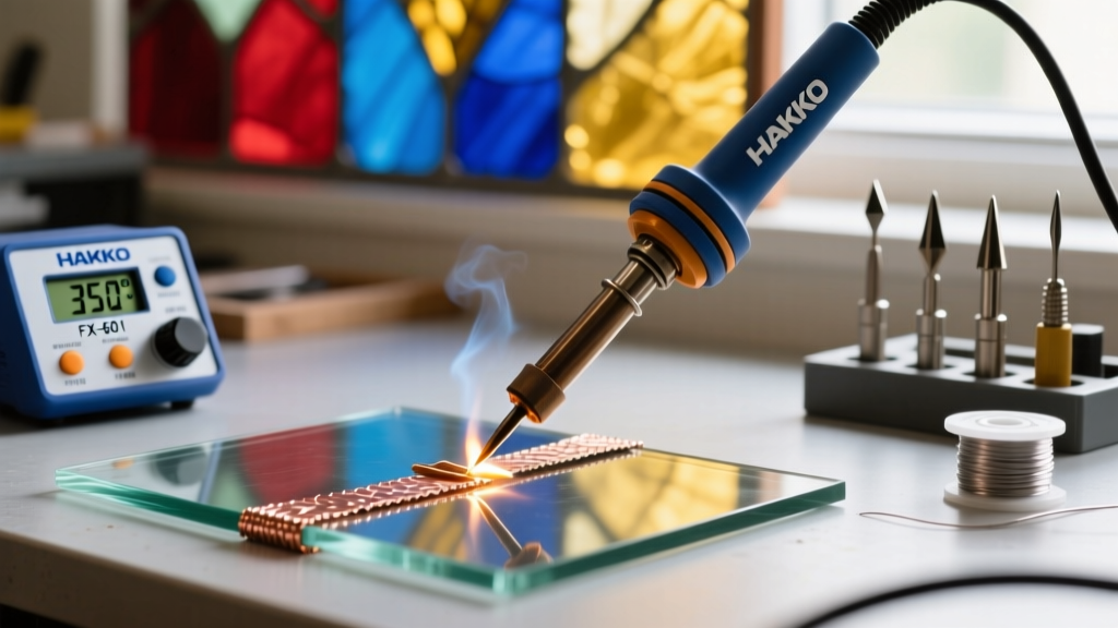
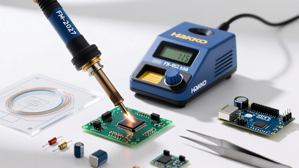
Modern professional stations define themselves by their Proportional-Integral-Derivative (PID) control loops. According to technical specifications from Hakko, modern digital stations sample the thermocouple embedded in the tip multiple times per second. The PID algorithm calculates the error between the setpoint and the actual temperature, adjusting the power output dynamically to prevent overshoot and ensure rapid thermal recovery when the tip contacts a cold PCB pad.
Direct-Drive and RISC-V Architectures
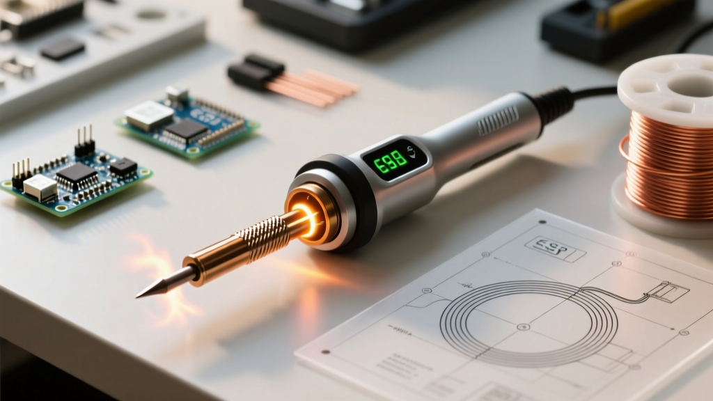
In 2026, open-source tools like the Pinecil V2 have disrupted the market by utilizing RISC-V microcontrollers capable of sampling temperatures and adjusting PWM (Pulse Width Modulation) outputs up to 10 times per second. This direct-drive architecture rivals $500 industrial stations at a fraction of the cost, redefining what hobbyists and field-repair technicians can expect from portable gear.
IPC Standards and the Definition of a Proper Joint
You cannot fully define the tool without defining its intended output. The IPC-A-610 standard for Acceptability of Electronic Assemblies defines a Class 3 (High-Performance) solder joint as having a smooth, shiny, or matte finish (depending on the specific lead-free alloy) with a wetting angle of less than 90 degrees.
A proper solder joint is not merely 'glued' together; it is a metallurgical alloy. The soldering iron must deliver precise heat to form an Intermetallic Compound (IMC) layer without exceeding the thermal degradation threshold of the PCB substrate.
Furthermore, NASA's Electronic Parts and Packaging (NEPP) program emphasizes that the iron must deliver sufficient heat to form a proper intermetallic compound (IMC) layer—typically 1 to 3 microns thick—without causing thermal damage to the substrate or component leads. If the iron is underpowered, the operator will compensate by holding the tip to the pad for too long, risking pad delamination and internal component damage.
Failure Modes: How Poor Thermal Definition Destroys Components
When operators fail to define their soldering iron requirements correctly, specific failure modes emerge on the assembly line:
- Tombstoning (Drawbridging): Caused by uneven pad heating. If the iron tip geometry does not bridge both pads of a small SMD component simultaneously, the solder on the hotter pad melts first, and surface tension pulls the component upright.
- Pad Delamination: Occurs when using an underpowered iron on a ground plane. The operator exceeds the IPC-recommended 3-second dwell time per joint, transferring excessive ambient heat into the FR4 substrate and breaking the epoxy bond.
- IMC Overgrowth: If an operator defines their workflow with an iron set to 400°C to 'speed things up', the excessive heat causes the IMC layer to grow too thick. Thick IMC layers are highly brittle and will fracture under minor mechanical or thermal shock in the field.
2026 Buying Framework: Defining Your Specific Requirement
To help you select the right tool, we have categorized the market based on how different user profiles define their needs in 2026:
1. The Field Technician & Hobbyist
Model: Pine64 Pinecil V2
Price Range: $26 - $35
Definition: A portable, PD-powered smart iron. It relies on USB-C Power Delivery (up to 65W) and features an open-source RISC-V backend. It is perfect for drone repair, automotive diagnostics, and bench hobbyists who need rapid thermal recovery without investing in a benchtop station.
2. The Prosumer & Small Repair Shop
Model: Hakko FX-888D
Price Range: $105 - $120
Definition: The undisputed workhorse of the mid-tier market. It features a robust 70W ceramic heater and a digital PID interface. While the UI is dated, its thermal mass and tip ecosystem (T18 series) make it a highly reliable, easily serviceable tool for daily through-hole and SMD repair.
3. The Industrial & Aerospace Assembly Line
Model: Weller WX2021 Soldering Station
Price Range: $450 - $550
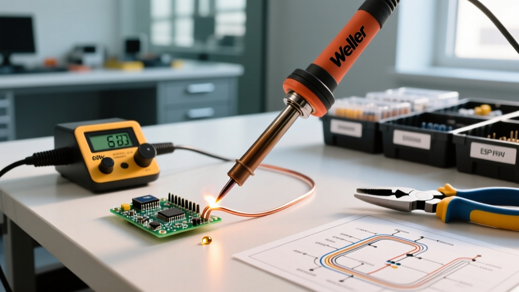
Definition: A high-end, smart-connected station designed for Class 3 IPC compliance. It features active tip recognition, user-lockout capabilities for QA enforcement, and a 200W power reserve capable of driving massive thermal loads without breaking a sweat. This defines the cutting edge of controlled thermal transfer.
Conclusion
To define a soldering iron accurately, one must look past the plastic handle and the heating element. It is a precision instrument of thermal transfer, governed by metallurgy, PID algorithms, and strict industry standards. By understanding the interplay between tip geometry, thermal mass, and closed-loop feedback, you can select a tool that not only melts solder but creates reliable, high-integrity metallurgical bonds that stand the test of time.