
The Critical Role of Thermal Accuracy in PCB Assembly
When setting up an electric soldering iron for precision printed circuit board (PCB) work, factory defaults are rarely sufficient for professional-grade results. Whether you are assembling delicate surface-mount devices (SMDs) or soldering heavy ground planes, the actual temperature at the tip of your iron frequently deviates from the digital readout on the station's display. This discrepancy, known as thermal offset, can lead to cold solder joints, component delamination, or catastrophic pad lifting.
According to the NASA Workmanship Standards for soldering, a reliable solder joint requires precise thermal profiling to ensure proper wetting and intermetallic compound (IMC) formation. If your electric soldering iron reads 350°C but the tip is actually outputting 320°C, your lead-free SAC305 solder paste will fail to reflow correctly, resulting in dull, grainy, and mechanically weak connections. This comprehensive tutorial will guide you through the exact setup, calibration, and maintenance procedures required to achieve IPC-compliant solder joints.
Understanding Your Electric Soldering Iron's Thermal Architecture
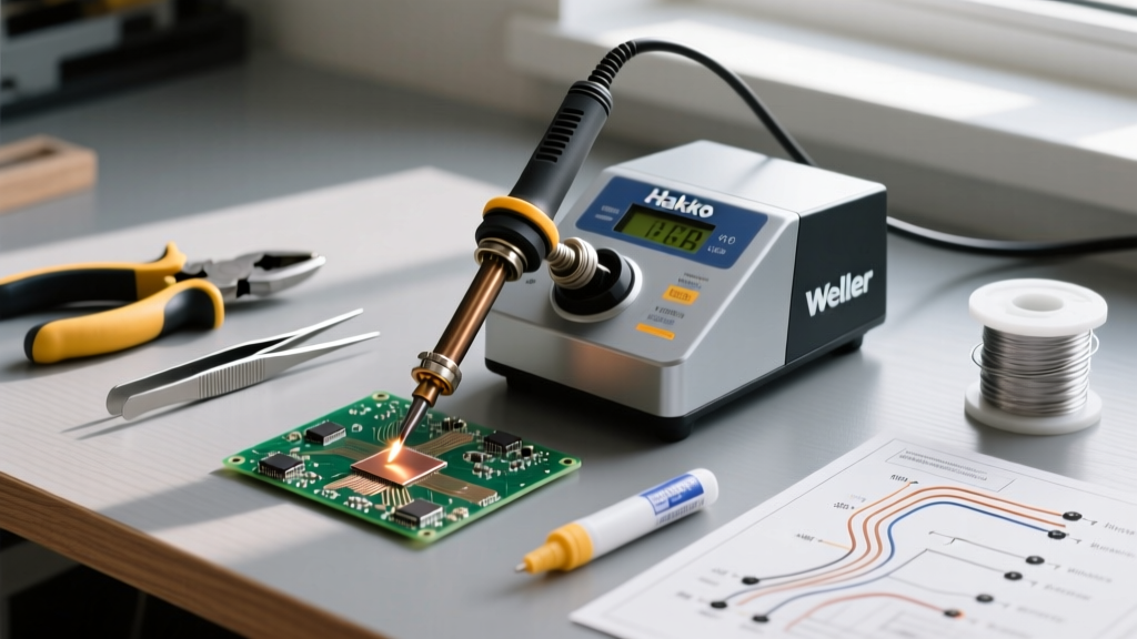
Before adjusting any settings, it is vital to understand how modern soldering stations measure heat. In a standard ceramic heating element—such as the Hakko T18 or Weller RT series—the thermocouple is embedded inside the heater core, not at the very tip of the iron. The station's microcontroller reads the voltage from this internal thermocouple and calculates the tip temperature based on a predefined thermal transfer curve.
However, this calculation assumes perfect physical contact between the heater core and the soldering tip. In reality, microscopic layers of oxidation, flux carbon buildup, and manufacturing tolerances create thermal resistance. This means a brand-new electric soldering iron might have an inherent offset of ±5°C to ±15°C right out of the box. As the tip ages and the internal plating degrades, this sensor drift can exceed 25°C, making manual calibration an absolute necessity for high-reliability electronics work.
Essential Calibration Tools and Equipment
You cannot calibrate a precision instrument using guesswork. To properly calibrate your electric soldering iron, you need a secondary, highly accurate temperature measurement device. Do not rely on cheap, unbranded infrared thermometers; they cannot read the emissivity of a polished metal tip accurately.
- Hakko 191 Tip Thermometer ($220 - $250): The industry standard for measuring soldering tip temperatures. It uses a specialized K-type thermocouple probe with a built-in thermal compound pad to ensure accurate heat transfer.
- Fluke 80PK-1 Bead Probe ($110 - $130): An excellent alternative K-type probe that can be paired with a high-quality multimeter like the Fluke 87V.
- Thermal Interface Paste: A small dab of high-temperature thermal paste (like Arctic Silver) is critical when using flat-surface probes to eliminate air gaps between the probe and the iron tip.
- Brass Wire Sponge & Damp Cellulose Sponge: For tip cleaning prior to measurement. Never use abrasive sandpaper or steel wool, which will destroy the iron-clad plating.
Step-by-Step Calibration Procedure
The following procedures apply to the two most common professional stations in 2026: the Hakko FX-888D and the Weller WE1010NA. Ensure your station has been powered on for at least 10 minutes to allow the internal electronics to reach thermal equilibrium.
Phase 1: Baseline Measurement
- Install a clean, well-tinned chisel tip (e.g., Hakko T18-D24 or Weller RT4). Conical tips are too small for accurate probe placement.
- Set the station to a standard lead-free working temperature: 350°C (662°F).
- Apply a tiny amount of thermal paste to the flat surface of the tip.
- Press the Hakko 191 sensor probe firmly against the tinned area. Wait 15 to 20 seconds for the reading to stabilize.
- Record the actual temperature. If the station reads 350°C but the probe reads 338°C, your offset is -12°C.
Phase 2: Entering Calibration Mode
For Hakko FX-888D:
- Turn the station power OFF.
- Press and hold the UP arrow button on the front panel.
- While holding UP, turn the power ON. The display will show '888'.
- Release the UP button, then press it once more to enter the calibration menu.
- Use the UP/DOWN buttons to select the tip group (e.g., T18), then press ENTER.
- Input the actual temperature measured by your external thermometer and press ENTER to save the offset.
For Weller WE1010NA:
- Ensure the station is ON and the iron is in the holder.
- Press and hold both the UP and DOWN buttons simultaneously for 3 seconds.
- The display will flash 'CAL'.
- Use the UP/DOWN buttons to adjust the displayed temperature until it matches your external probe's reading.
- Press the SET button to lock in the new calibration offset.
Calibration Offset Matrix by Tip Geometry
Different tip shapes dissipate heat at vastly different rates. A heavy-duty chisel tip will retain heat and read closer to the core sensor, while a micro-conical tip will lose heat rapidly to the ambient air. Below is a reference matrix for typical offsets observed during electric soldering iron setup.
| Tip Geometry | Target Temp (°C) | Typical Measured Temp (°C) | Required Offset Adjustment | Best Use Case |
|---|---|---|---|---|
| Heavy Chisel (3.2mm) | 350°C | 346°C | +4°C | Through-hole, heavy ground planes |
| Standard Bevel (1.6mm) | 350°C | 338°C | +12°C | General SMD, 0805/0603 components |
| Micro-Conical (0.4mm) | 350°C | 325°C | +25°C | Fine-pitch QFP, 0402 passives |
| Knife / Blade (K-Tip) | 350°C | 340°C | +10°C | Drag soldering, PCB rework |
Troubleshooting Thermal Lag and Sensor Drift
Even after a perfect calibration, you may encounter scenarios where your electric soldering iron fails to maintain temperature during active soldering. Understanding these failure modes is critical for advanced PCB rework.
1. The 'Cold Joint' Paradox (High Thermal Mass)
If you are soldering a large copper pour (like a motherboard ground plane) and the solder refuses to flow, the issue is not necessarily the iron's calibration, but its thermal recovery rate. The IPC Standards dictate that a joint must reach the solder's liquidus temperature within 2 to 4 seconds. If your 60W station cannot recover heat fast enough, you must switch to a higher wattage station (like the Hakko FX-951 or JBC CD-2BE) rather than simply increasing the temperature dial, which risks burning the flux and oxidizing the pad.
2. Thermocouple Degradation
If your station displays erratic temperature swings (e.g., jumping from 340°C to 380°C and back), the internal K-type thermocouple in the handpiece is likely failing. According to NIST Calibration Services documentation, base-metal thermocouples experience drift over time due to oxidation and metallurgical changes at high temperatures. If recalibration fails to stabilize the reading, the heating element core must be replaced.
3. Poor Tip Seating
A common setup error is failing to fully seat the tip onto the heating element. If the retaining nut is loose, or if there is a layer of burnt flux between the element and the inside of the tip, thermal transfer is choked. Always clean the heating element with isopropyl alcohol (IPA) and a lint-free swab before installing a new tip.
Expert Insight: Never calibrate an electric soldering iron using a dry tip. Always ensure the tip is heavily tinned with fresh solder before applying the thermal probe. The solder acts as a thermal bridge; without it, the probe will read ambient air temperatures trapped in microscopic surface imperfections, resulting in a falsely low reading and a dangerous over-calibration.
Maintenance Schedule for Long-Term Accuracy
Calibration is not a one-time event. To maintain IPC Class 2 and Class 3 compliance, implement the following maintenance schedule for your soldering equipment:
- Daily: Tin the tip heavily before powering down the station. This sacrificial layer of solder prevents the iron plating from oxidizing overnight.
- Weekly: Inspect the tip under a magnifying lamp for pitting or black oxide buildup. Clean with a damp cellulose sponge, never cold water, which causes thermal shock and micro-fractures in the ceramic heater.
- Monthly: Verify the calibration offset using a tip thermometer. If the offset has drifted by more than 5°C since the last check, recalibrate immediately.
- Annually: Replace high-use tips. Even with perfect maintenance, the iron-clad plating on a tip will eventually dissolve into the molten solder, exposing the copper core to rapid degradation.
Final Thoughts on Precision Soldering
Mastering the setup and calibration of your electric soldering iron transforms it from a basic heating tool into a precision metallurgical instrument. By understanding the thermal architecture of your station, utilizing high-quality measurement probes, and adhering to a strict maintenance schedule, you ensure that every joint you create meets the rigorous demands of modern electronics manufacturing. Whether you are repairing a multi-layer server motherboard or assembling a custom mechanical keyboard, accurate temperature control is the foundation of flawless soldering.