
The Transformer Advantage: Why Weller Guns Are Unique
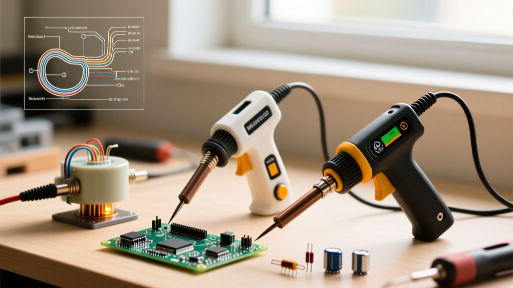
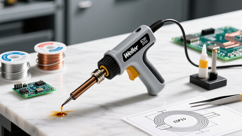
Mastering how to use a Weller soldering gun requires a fundamental grasp of its internal architecture. Unlike modern ceramic-heater soldering stations that rely on resistive heating elements and PID temperature controllers, a classic Weller gun—like the ubiquitous Weller 8200 (100/140W) or the heavy-duty D550 (200/260W)—operates as a high-current step-down transformer.
When you pull the trigger, 120V AC passes through the primary coil, inducing a massive current in the single-turn secondary copper loop. This steps the voltage down to roughly 0.2V–0.5V while pushing 200 to 600 amps through the soldering tip. The tip's inherent electrical resistance generates instantaneous heat via the $I^2R$ formula. This unique physics profile means Weller guns heat up in 3 to 5 seconds, making them unparalleled for heavy-gauge wiring, stained glass, and large grounding planes. However, this same design demands specific operational techniques and rigorous maintenance to prevent catastrophic tip failure and transformer burnout.
Core Operation: The Dual-Stage Trigger Technique
A common mistake among novices learning how to use a Weller soldering gun is mashing the trigger to the maximum setting immediately. The dual-stage trigger is engineered for thermal management, not just binary on/off control.
- Stage One (Low Heat): On the Weller 8200, the first pull engages the 100W tap. Use this to pre-heat large thermal masses, such as 10 AWG copper wire or heavy chassis lugs, without shocking the joint or oxidizing the flux prematurely.
- Stage Two (High Heat): Squeezing fully engages the 140W tap. Apply this only when the joint is near flow temperature and you need to melt high-temperature lead-free alloys (like SAC305) or overcome massive heat sinking.
Because the secondary loop acts as a powerful electromagnet, the stray magnetic field can induce destructive gate voltages in unprotected MOSFETs, CMOS logic, and sensitive Hall-effect sensors. Never use a transformer gun on populated, sensitive PCBs. Reserve it for passive components, heavy wiring, and mechanical chassis grounds.
Routine Maintenance: Extending Element and Tip Life
Weller tips are constructed from a copper core plated with iron to prevent solder dissolution. Once that iron plating is breached, the molten solder will eat through the copper core in a matter of hours. As of early 2026, a replacement CT6C7 heating element retails for approximately $14 to $18, while standard CT6A8 tips cost around $7 to $9. Protecting these consumables is vital for cost-effective operation.
The Golden Rules of Tip Care
- Never File the Tip: Filing removes the protective iron plating, instantly destroying the tip. If oxidation occurs, use a damp cellulose sponge or a dry brass wire sponge.
- Always Re-Tin Before Power-Off: The moment you release the trigger, melt a generous bead of rosin-core solder over the working end of the tip. As the gun cools, this solder solidifies, creating an airtight seal that prevents high-temperature oxidation from pitting the iron layer.
- Check the Tip Nuts Weekly: The secondary circuit relies on a zero-resistance mechanical connection between the copper element loop and the steel tip. Vibration from the 60Hz transformer hum loosens the aluminum retaining nuts over time. Tighten them using the provided stamped steel wrench—never use pliers, which will strip the soft aluminum threads.
Troubleshooting Matrix: Diagnosing Common Weller Failures
When your tool stops performing, use this diagnostic matrix to identify the root cause before replacing expensive components.
| Symptom | Root Cause | Corrective Action |
|---|---|---|
| Loud 60Hz hum, no heat or slow heating | Loose tip nuts causing micro-arcing; oxidized contact surfaces between tip and element. | Remove tip and nuts. Clean threads and contact pads with isopropyl alcohol and a fiberglass scratch pen. Re-seat and tighten evenly. |
| Tip turns black and pits within minutes | Use of acid-core plumbing flux; operating on Stage 2 continuously; dry-firing without solder. | Switch to electronics-grade rosin (RMA) or no-clean flux. Discard pitted tip. Use Stage 1 for 80% of the heating cycle. |
| Intermittent heating; trigger feels 'mushy' | Carbon buildup on the internal dual-stage microswitch contacts from high inrush current arcing. | Disassemble the ABS handle. Remove the microswitch and burnish the internal copper contacts lightly with contact cleaner and a paper slip. |
| Illumination bulb burns out instantly | Using a standard 12V automotive bulb instead of a Weller-specific high-vibration, low-voltage transformer tap bulb. | Replace with the exact OEM Weller B500 or equivalent 13V heavy-duty lamp designed to withstand transformer inrush spikes. |
Deep Dive: Replacing the Heating Element Safely
If the primary winding burns out or the secondary copper loop cracks from mechanical stress, the element must be replaced. Weller, now a flagship brand under the Apex Tool Group umbrella, designs these elements for straightforward field replacement.
- Isolate Power: Unplug the gun. Never rely solely on the trigger switch for isolation during internal maintenance.
- Disassemble the Handle: Remove the four Phillips-head screws securing the two halves of the thermoplastic handle. Carefully separate the halves, noting the routing of the primary power cord and the strain relief clamp.
- Remove the Old Element: Using a 1/4-inch nut driver, remove the two nuts securing the element loop to the internal transformer bus bars. Note the orientation of the ceramic insulators.
- Clean the Bus Bars: Use a brass wire brush to remove any oxidation from the transformer bus bar terminals to ensure maximum current transfer.
- Install the New CT6C7 Element: Seat the new element loop, ensuring the ceramic insulators are perfectly aligned to prevent the secondary loop from shorting against the transformer core laminations.
- Torque and Reassemble: Tighten the bus bar nuts firmly but avoid over-torquing, which can snap the copper loop. Route the trigger wires carefully to prevent pinching when snapping the handle halves back together.
Authoritative Standards and Safety Protocols
Professional soldering requires adherence to industry standards to ensure joint reliability and operator safety. According to the IPC J-STD-001 standard for soldered electrical and electronic assemblies, thermal profiles must be strictly managed to prevent dielectric damage and cold solder joints. Because Weller guns lack closed-loop temperature feedback, the operator must visually monitor the flux activation and solder flow states to comply with IPC thermal dwell time limits.
Furthermore, when working with traditional Sn60/Pb40 or Sn63/Pb37 wire, always adhere to OSHA guidelines on lead hazard management. The rapid heating of a Weller gun can generate dense plumes of colophony (rosin) fumes and lead particulates. Always utilize a localized HEPA and activated carbon fume extractor positioned within 6 inches of the joint.
Expert FAQ: Edge Cases and Limitations
Can I use a Weller gun for delicate SMD components?
No. The thermal mass and rapid heat transfer of a Weller gun will instantly delicate surface-mount pads, melt plastic connector housings, and destroy 0402 or 0603 components. Furthermore, the magnetic field generated by the tip loop can magnetize nearby inductors or induce currents that fry sensitive silicon. For SMD work, use a temperature-controlled micro-pencil station with a J-lead or chisel tip.
Why does my soldering gun tip turn black instantly, even with rosin flux?
If you are using genuine electronics-grade rosin flux and the tip still oxidizes instantly, you are likely 'dry-firing' the gun. Holding the Stage 2 trigger without transferring heat into a joint or applying solder causes the tip temperature to exceed 900°F (482°C). At this threshold, the iron plating undergoes rapid thermal oxidation, turning black and refusing to wet. Always introduce solder to the tip the moment it reaches flow temperature to act as a thermal buffer and oxygen barrier.
Is it normal for the transformer to buzz loudly?
A moderate 60Hz hum is the physical reality of the AC magnetic field vibrating the transformer's steel laminations. However, a violent, rattling buzz indicates loose laminations or, more commonly, a poor mechanical connection at the tip nuts causing micro-arcing. If the buzz is accompanied by a smell of ozone or burning varnish, unplug the tool immediately and inspect the tip connections and primary winding insulation.