
Understanding the C245 Ecosystem in 2026
The JBC C245 cartridge standard remains the undisputed champion for mixed-technology electronics work, bridging the gap between heavy ground-plane through-hole soldering and ultra-fine 0201 SMD rework. Unlike legacy soldering irons that rely on a separate ceramic heating element and a hollow tip, the C245 system integrates the heater, thermocouple, and tip into a single, disposable cartridge. This design allows for a thermal recovery time of under two seconds and a maximum power delivery of 65 watts.
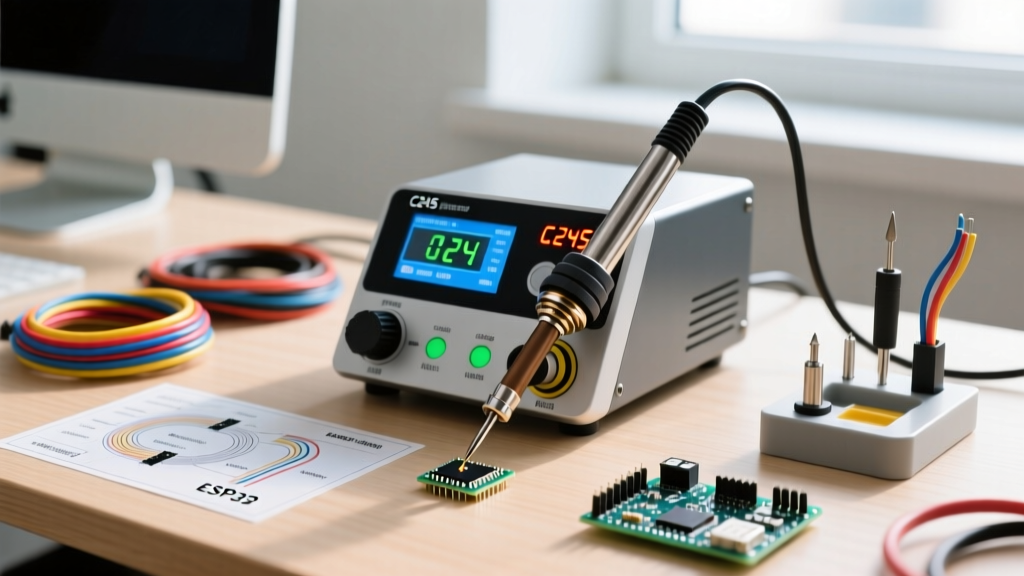
As of 2026, the market is flooded with both genuine JBC stations (like the CD-2BE) and high-performance C245-compatible clone controllers (such as the AiXun T3A, Sequre, and Pine64 adapter ecosystems). While the cartridges are largely cross-compatible, the setup, pinout verification, and thermal calibration processes require strict adherence to best practices to avoid damaging the internal micro-thermocouple or the station's MOSFET drivers.
CRITICAL CLONE WARNING: If you are wiring a custom C245 handle or using a third-party adapter board, never assume the aviation plug pinout matches genuine JBC hardware. Swapping the Thermocouple+ and Heater- pins will instantly send 24V DC into your station's low-voltage ADC, permanently destroying the microcontroller's analog read circuit.Phase 1: Physical Setup and Cartridge Seating
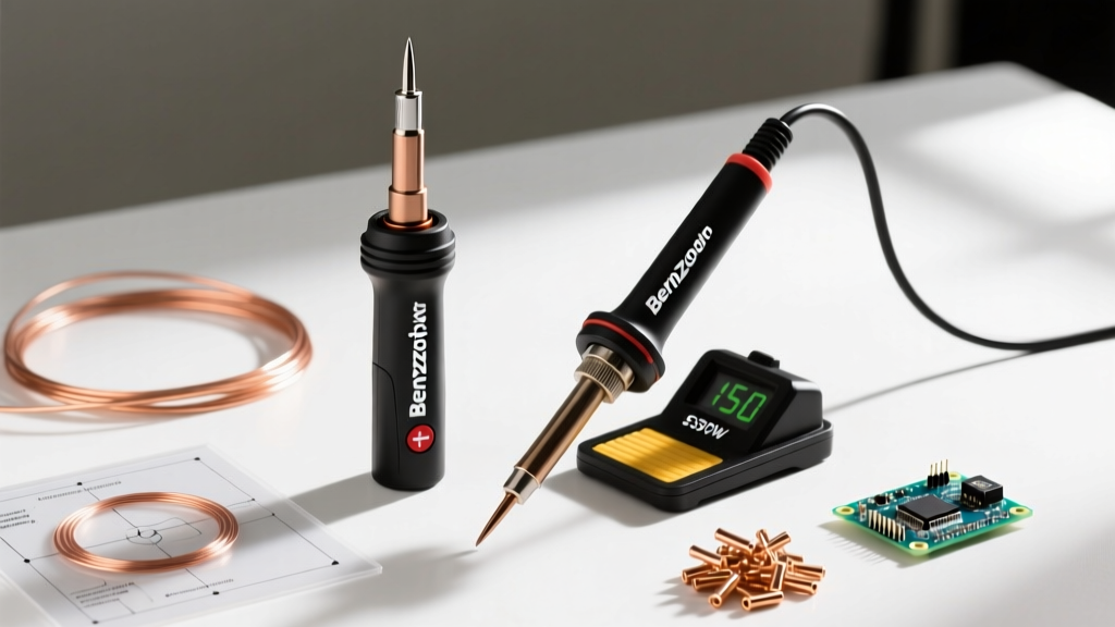
Proper physical setup is the foundation of accurate thermal transfer. The C245 cartridge features four contact pads on its base that mate with the internal spring-loaded pogo pins inside the T245 handle.
The 'Push-Only' Insertion Rule
The most common failure mode for new C245 users is cracking the internal ceramic substrate. This occurs when users attempt to twist or screw the cartridge into the handle to 'ensure a good connection.' You must never twist a C245 cartridge. The correct procedure is:
- Ensure the station is powered off to prevent arcing across the contact pads.
- Align the cartridge with the handle's keyway notch.
- Push the cartridge straight in with firm, even pressure until you feel it seat against the internal pogo pins.
- Secure the cartridge by tightening the handle's external locking nut or sliding the silicone grip sleeve forward, depending on your specific handle model.
Phase 2: Thermal Offset Calibration
Even premium stations require periodic thermal offset calibration. Over time, the metallurgical bond between the cartridge's iron plating and the internal thermocouple degrades, leading to a phenomenon known as 'thermal drift.' If your station displays 350°C but the actual tip surface is 335°C, you will experience cold solder joints and pad lifting when working with modern SAC305 lead-free alloys.
For this calibration, you will need a K-type tip thermometer (such as the Hakko FG-100B or Weller WSD-100) and a small amount of fresh, high-flux solder paste.
Step-by-Step Calibration Procedure
- Prep the Tip: Clean the C245 cartridge using a dry brass wire sponge. Never use a wet cellulose sponge; the rapid temperature drop causes micro-fractures in the ceramic heater core.
- Apply Thermal Interface: Melt a small bead of fresh SAC305 solder onto the tip. This solder acts as a thermal bridge between the tip and the thermometer's K-type probe.
- Set Baseline: Set your C245 soldering station to exactly 350°C and allow it to stabilize for 45 seconds after the heater indicator turns off.
- Measure: Gently press the K-type probe into the molten solder bead on the tip. Wait for the thermometer reading to stabilize (usually 3-5 seconds).
- Calculate Offset: If the station reads 350°C and the thermometer reads 342°C, your offset is -8°C. Access your station's hidden calibration menu (usually accessed by holding the encoder knob and power button simultaneously on clone stations, or via the JBC menu system) and apply a +8°C positive offset.
- Verify: Repeat the measurement at 300°C and 380°C to ensure the thermal curve is linear. If the curve is non-linear (e.g., accurate at 300°C but 15°C off at 380°C), your cartridge's internal thermocouple is failing and must be replaced.
C245 Cartridge Selection Matrix
Selecting the correct cartridge geometry is just as critical as calibration. Using a tip that is too small for a large ground plane will cause the station to max out its 65W duty cycle, leading to premature tip oxidation. Below is a curated selection guide for 2026 SMD and THT workflows.
| Cartridge SKU | Geometry & Size | Primary Use Case | Thermal Mass |
|---|---|---|---|
| C245-945 | Chisel 2.2mm | General 0805 SMD, standard THT, wire tinning | Medium |
| C245-746 | Knife / Blade | Drag soldering QFP/QFN ICs, scraping traces | High |
| C245-105 | Conical 0.4mm | Precision 0402/0201 passives, micro-BGA rework | Low |
| C245-903 | Bevel 1.5mm | Large SMD pads, coaxial shielding, heavy wires | High |
For a comprehensive list of OEM geometries and their exact thermal recovery metrics, refer to the official JBC C245 cartridge catalog.
Phase 3: Tuning Sleep and Boost Parameters
Modern C245 soldering stations feature intelligent sleep modes that drastically extend cartridge lifespan. The iron plating on a C245 tip dissolves into molten solder at an exponential rate as temperatures exceed 380°C. By properly configuring your station's standby parameters, you can double the usable life of your cartridges.
Recommended Thermal Profiles
- Active Soldering (Lead-Free SAC305): 350°C - 370°C. This aligns with the IPC J-STD-001 standard for reliable intermetallic compound (IMC) formation without causing thermal damage to FR4 laminates.
- Active Soldering (Leaded Sn63/Pb37): 320°C - 335°C.
- Standby / Sleep Mode: 175°C. At this temperature, the flux core inside your solder wire will not spontaneously combust or carbonize when the tip rests in the holder, but the station can still wake up to 350°C in under 3 seconds.
- Auto-Sleep Timeout: 13 minutes. This is the JBC factory default and is proven to be the optimal balance between workflow interruption and tip preservation.
Expert Insight on Oxidation: According to the NASA Workmanship Standards for soldered electrical assemblies, prolonged exposure of iron-plated tips to high temperatures in ambient air causes rapid oxidation, rendering the tip non-wettable. Always leave a large 'blob' of sacrificial solder covering the entire working surface of the C245 cartridge before placing it into the sleep stand. This sacrificial blob oxidizes instead of the tip's iron plating.
Troubleshooting Common C245 Errors
When setting up a C245 soldering station, especially when integrating third-party handles, you may encounter specific error codes on the station's OLED display. Here is how to diagnose the most frequent hardware faults:
- H20 / Open Circuit Error: The station cannot detect the heater coil. This is almost always caused by a broken wire inside the silicone handle cable near the strain relief, or a cartridge that was not pushed in fully. Reseat the cartridge and flex the cable while monitoring the display. If the error flickers, replace the handle cable.
- H21 / Short Circuit Error: The heater pins are shorted to the thermocouple pins. This usually indicates internal catastrophic failure of the cartridge's ceramic substrate. Discard the cartridge immediately; continuing to supply power can damage the station's MOSFETs.
- Erratic Temperature Readings (Jumping >20°C): The ADC is receiving noisy thermocouple data. Check the handle's aviation plug for oxidation. Clean the pins with 99% isopropyl alcohol and a fiberglass scratch pen. Ensure the station is plugged into a grounded outlet, as ungrounded switching power supplies can inject high-frequency EMI into the low-voltage thermocouple lines.
Final Verification and Maintenance
Once your C245 soldering station is calibrated and your sleep profiles are configured, perform a final practical test. Attempt to solder a 14-pin SOIC chip on a board with a heavy ground plane. If the solder flows instantly and forms a smooth, concave fillet without requiring you to hold the iron in place for more than two seconds per pad, your thermal offset and cartridge selection are perfectly dialed in. Re-calibrate your station every 6 months, or immediately after dropping the handle, to ensure absolute thermal accuracy.