
Why 100 Watts? Understanding Thermal Mass and Recovery
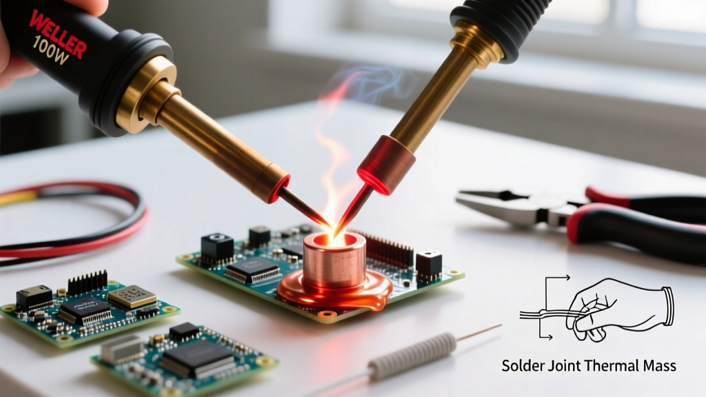
When transitioning from delicate surface-mount components to heavy-duty electrical assemblies—such as 8 AWG battery leads, XT90 connectors, or thick copper ground planes—a standard 40W to 60W iron simply falls short. The core issue is not maximum temperature, but thermal recovery. When a low-wattage tip contacts a high-thermal-mass joint, the copper acts as a massive heat sink, instantly dropping the tip temperature below the solder's liquidus phase. The result is a cold, crystallized joint that fails under mechanical or electrical load.
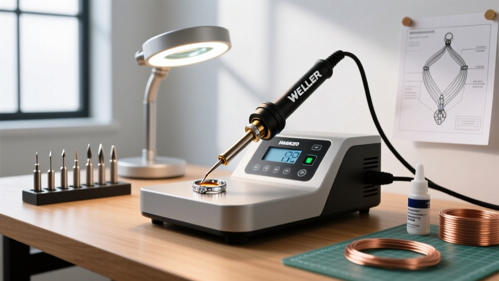
This is where a Weller 100W soldering iron proves its worth. Whether you are using the legendary Weller SP100N heavy-duty spotlight iron (retailing around $55 in 2026) or the W100H 100W replacement tool for WES/WEC stations (approximately $90), the 100-watt ceramic or magnastat heater core provides the continuous thermal current required to keep the joint above the melting point of the solder alloy during the critical wetting phase.
Expert Insight: Wattage dictates how fast an iron can replenish lost heat, not how hot it gets. According to the IPC J-STD-001 standard, proper wetting requires the base metals to reach the solder's melting point simultaneously. A 100W iron ensures the delta-T (temperature difference) remains stable even when dumping heat into a 4 AWG copper strand.
Selecting the Right Tip Geometry for High-Mass Joints
Having 100 watts of power is useless if the tip geometry cannot transfer that heat into the joint efficiently. For heavy-duty work, you must maximize the surface area contact between the tip and the workpiece. Conical tips are entirely unsuitable for thick wires, as they offer a microscopic contact patch and will pit or oxidize rapidly under high-heat stress.
Below is a breakdown of the optimal Weller tip geometries for high-thermal-mass applications:
| Tip Model | Geometry | Best Application | Est. Dwell Time (10 AWG) |
|---|---|---|---|
| CT6F7 (W100H) | 1/4" Screwdriver | Large through-hole tabs, thick ground planes | 3.5 - 4.5 seconds |
| SP400N (SP100N) | Heavy Chisel | Battery tabs, heavy stranded wire splicing | 2.5 - 3.5 seconds |
| CT6C7 (W100H) | 1/8" Bevel | Cupping for round wire joints, pre-tinning | 4.0 - 5.0 seconds |
For the absolute best thermal transfer on stranded wire, the heavy chisel or wide screwdriver tip allows you to 'wrap' the heat around the cylindrical wire bundle, ensuring the core strands reach the necessary temperature before the outer strands overheat and melt the insulation.
Step-by-Step Technique: Soldering 8 AWG to 4 AWG Wire
Soldering thick gauge wire requires a disciplined sequence to prevent flux burn-off and insulation melt-back. Follow this precise methodology for bulletproof connections.
1. Mechanical Preparation and Pre-Tinning
Strip exactly 3/8" to 1/2" of insulation. Do not twist the strands tightly; a gentle lay is sufficient to maintain capillary action. Apply a high-solids rosin flux, such as Kester 186, to the bare copper. Set your Weller 100W soldering iron to 750°F (400°C) for 63/37 leaded solder, or 820°F (438°C) if using SAC305 lead-free alloy.
2. The Individual Pre-Tin
Never attempt to solder two bare wires together simultaneously. Pre-tin each wire individually. Apply the flat face of the chisel tip to the wire, wait 1.5 seconds for the flux to activate (you will see it bubble and smoke), and feed 0.062" (1.5mm) diameter rosin-core solder into the wire, not the iron tip. The solder should wick instantly to the base of the strands.
3. The Mating Phase
Overlap the two pre-tinned wires or insert them into a heavy ring terminal. Apply the 100W tip directly to the bulk of the copper. Because both surfaces are already tinned, you will not need to feed much additional solder. The existing solder will re-flow and merge into a single, shiny fillet within 3 to 4 seconds.
4. The Withdrawal and Cooling
Remove the solder wire first, then withdraw the iron in a single, fluid motion. Do not blow on the joint. Forced air cooling on high-mass joints can cause thermal shock, leading to micro-fractures in the solder crystalline structure. Allow the joint to cool naturally for 5 seconds before moving the assembly.
Metallurgy Considerations: Leaded vs. Lead-Free at 100W
When wielding a Weller 100W soldering iron, your choice of solder alloy drastically alters your technique. Standard 63/37 (Tin/Lead) eutectic solder melts at a crisp 361°F (183°C) and transitions instantly from liquid to solid. This is highly forgiving for beginners working on thick wires.
However, modern commercial and aerospace repairs often mandate SAC305 (Tin/Silver/Copper) lead-free solder. SAC305 melts between 424°F and 432°F (217°C - 222°C) and possesses a 'pasty' range where it is semi-solid. If you move an 8 AWG wire while a SAC305 joint is in this pasty range, you will create a disturbed joint, which expert soldering guides identify as a primary cause of high-resistance failures. When using SAC305 with your 100W Weller, you must increase your dwell time by roughly 1.5 seconds to ensure the entire thermal mass crosses the liquidus threshold, and you must hold the wire absolutely rigid until the joint dulls and solidifies completely.
Troubleshooting Common High-Wattage Failures
Even with 100 watts of power, poor technique will yield defective joints. Watch for these specific failure modes:
- Dry Tip Oxidation: At 800°F+, an un-tinned Weller tip will oxidize and turn black in under 45 seconds, creating an insulating layer of copper oxide that blocks heat transfer. Fix: Always leave a thick blob of solder on the tip before placing it in the stand. Never wipe the tip completely dry with a brass sponge; leave a protective coating of molten solder.
- Insulation Melt-Back: Copper is an exceptional thermal conductor. If you apply the iron too close to the wire's jacket, the heat will wick under the insulation, melting it and exposing bare wire. Fix: Maintain a 1/4" gap between the iron contact point and the insulation. Use a hemostat or aluminum heat-sink clip on the wire if working near sensitive components.
- Flux Charring: If your dwell time exceeds 7 seconds, the rosin flux will burn into a hard, black carbon crust. This crust is mildly corrosive and prevents proper wetting on secondary passes. Fix: Remove the iron, clean the joint with 99% isopropyl alcohol and a stiff brush, re-apply fresh Kester 186 liquid flux, and attempt the joint again.
Maintaining Your Weller 100W Station
To ensure your Weller 100W soldering iron lasts for decades, routine maintenance of the heater core and tip interface is critical. For the W100H magnastat tools, the tip must seat fully against the internal sensor. If oxidation builds up inside the tip barrel, the thermal coupling fails, and the iron will run continuously without shutting off, eventually burning out the heating element. Once a month, remove the tip and clean the inside of the barrel and the outside of the sensor with a fiberglass scratch pen or fine emery cloth. For the SP100N, ensure the set screw holding the heavy chisel tip is tightened securely with a flathead screwdriver to prevent arcing between the element and the tip base.
Mastering a Weller 100W soldering iron bridges the gap between hobbyist electronics and professional electromechanical assembly. By respecting thermal mass, selecting the correct wide-geometry tips, and adhering to strict dwell-time protocols, you will produce joints that meet rigorous Weller engineering standards and withstand years of high-current vibration and thermal cycling.