
The Science of Thermal Plastic Welding
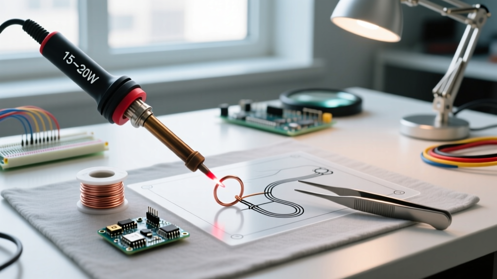
While soldering irons are traditionally reserved for joining metals with tin-lead or lead-free alloys, they are highly effective tools for thermal plastic welding. When repairing cracked 3D-printed enclosures, fixing automotive interior trim, or sealing DIY electronics housings, understanding how to weld plastic with a soldering iron provides a cost-effective alternative to ultrasonic welders or hot air stations. The core principle relies on bringing the polymer to its glass transition or melting phase without triggering thermal degradation, which releases toxic volatile organic compounds (VOCs) and weakens the molecular chain.
Success in plastic welding is not about brute heat; it is about precise thermal calibration and surface preparation. According to the British Plastics Federation, different polymers exhibit vastly different thermal behaviors. Applying standard electronics soldering temperatures (typically 350°C to 400°C) to a thermoplastic like ABS or PLA will instantly carbonize the material, resulting in a brittle, structurally void joint. This tutorial will guide you through the exact setup, calibration, and execution required to achieve structural plastic welds using standard benchtop soldering stations.
Identifying Your Plastic Resin and Thermal Thresholds
Before powering on your station, you must identify the base polymer. You cannot successfully weld dissimilar plastics; an ABS filler rod will not chemically bond to a polypropylene (PP) substrate. For DIY and electronics applications, you will primarily encounter the following thermoplastics. Use this calibration matrix to set your baseline temperatures.
| Polymer Type | Common Applications | Melting / Glass Transition Temp | Target Iron Calibration |
|---|---|---|---|
| PLA (Polylactic Acid) | 3D printed prototypes, hobby parts | 150°C - 160°C | 170°C - 185°C |
| ABS (Acrylonitrile Butadiene Styrene) | Electronics enclosures, automotive trim | 210°C - 240°C | 230°C - 250°C |
| PETG (Polyethylene Terephthalate Glycol) | Waterproof housings, mechanical parts | 230°C - 250°C | 245°C - 260°C |
| PP (Polypropylene) | Living hinges, chemical containers | 160°C - 170°C | 180°C - 195°C |
Calibrating Your Soldering Station for Plastics
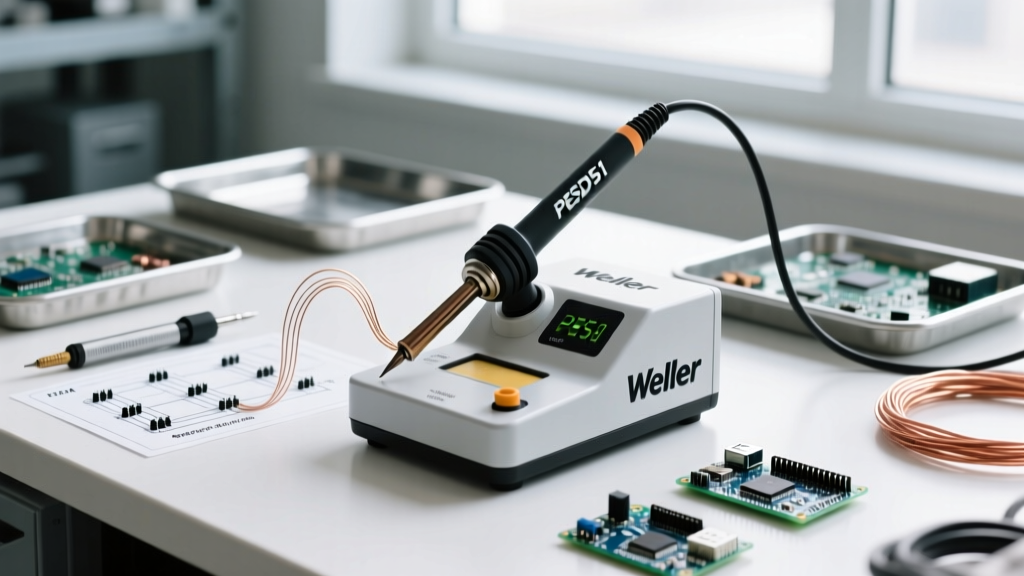
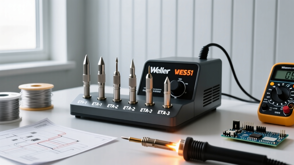
To maintain the tight thermal tolerances required for plastic welding, you must use a temperature-controlled station. Fixed-wattage irons (like standard 40W pencil irons) experience massive thermal droop when pressed against a heat-sinking plastic mass, leading to uneven melting and cold joints. We recommend stations with high thermal recovery rates, such as the Hakko FX-888D or the Weller WE1010NA, which utilize active feedback loops to maintain tip temperature within ±5°C.
Step 1: Selecting and Modifying the Tip Profile
Standard conical (B-series) or fine chisel tips used for 0402 SMD components are entirely unsuitable for plastic. They concentrate heat into a microscopic point, piercing the plastic and creating burn-holes rather than surface welds. You need a broad thermal footprint.
- The Broad Chisel: Select a heavy-duty chisel tip with a minimum 4mm to 6mm flat face. The Hakko D24 or Weller SMT series provide excellent thermal mass for drag-welding.
- The Custom Spatula: For wide seams, some technicians file down an old, degraded copper tip into a flat, rounded spatula shape to increase the surface contact area.
Step 2: The PTFE Non-Stick Barrier Technique
One of the most critical failure points in DIY plastic welding is the molten polymer adhering to the iron-plated copper tip. As you drag the iron, the plastic tears away from the substrate and wraps around the tip, creating a messy, weak joint.
Expert Calibration Trick: The PTFE Tape Barrier
Wrap your broad chisel tip in exactly two layers of standard 0.1mm PTFE (Teflon) plumber's thread seal tape. PTFE has a melting point of 327°C, meaning it will easily survive the 250°C required for ABS or PETG welding without degrading. This creates a high-temperature non-stick surface that allows the molten plastic to flow smoothly off the tip and into the joint. Replace the PTFE tape every 3 to 4 weld joints as it degrades mechanically from friction.
Execution: Joint Preparation and Welding Technique
Once your station is calibrated to the target temperature and your tip is prepped, you must prepare the physical joint. Unlike metal soldering, where capillary action draws flux and solder into a gap, plastic welding requires physical displacement and fusion of the base materials.
Preparing the Seam
For plastics thicker than 2mm, a simple butt joint will yield poor tensile strength. You must chamfer the edges to create a V-groove.
- Use a deburring tool or a coarse file to carve a 45-degree bevel along both mating edges, creating a 'V' channel when the pieces are pushed together.
- Clean the channel with isopropyl alcohol (IPA) to remove mold release agents, dust, and skin oils that inhibit molecular bonding.
- Secure the parts with high-temperature Kapton tape or metal binder clamps. The plastic will soften and warp if not mechanically constrained during the cooling phase.
Selecting a Filler Rod
Do not attempt to weld thick gaps using only the base material; you will warp the surrounding geometry. You need a filler rod. The most accessible, perfectly matched filler for DIYers is standard 1.75mm 3D printer filament. If you are welding an ABS enclosure, use ABS filament. For PLA, use PLA. This guarantees chemical compatibility and identical thermal expansion coefficients.
The Tack and Drag Method
- Tack Welding: Touch the PTFE-wrapped tip to the seam every 20mm to create localized tack welds. This locks the alignment before the main drag pass.
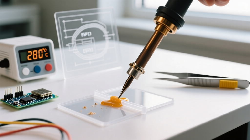
- Pre-heating: Rest the flat face of the iron in the V-groove for 2 to 3 seconds. Allow the base plastic to transition from solid to a glossy, semi-liquid state. Do not force the iron downward.
- Feeding the Filler: Introduce the 1.75mm filament into the leading edge of the iron tip. As the filament melts, push it down into the V-groove.
- The Drag: Slowly pull the iron along the seam at a rate of roughly 10mm per second. The iron should be melting the base material and the filler simultaneously, blending them into a single homogeneous puddle.
- Tooling the Bead: Immediately after the iron passes, use a flat, PTFE-coated spatula or a damp (not wet) silicone shaping tool to press the molten bead flat into the groove, eliminating voids and increasing surface contact.
Troubleshooting Common Weld Failures
Even with perfect calibration, environmental factors and technique errors can compromise the joint. Use this diagnostic guide to correct your process on the fly.
Failure Mode 1: Blackening, Smoking, and Brittle Joints
Diagnosis: Thermal degradation. Your iron is set too high, or you are moving too slowly, causing the polymer chains to break down (depolymerization). In ABS, this releases styrene gas and leaves a carbonized, structurally useless black residue.
Correction: Drop the station temperature by 15°C. Increase your drag speed. Ensure your fume extractor (such as a Hakko FA-400 with an activated carbon filter) is positioned within 3 inches of the weld zone to pull VOCs away from your breathing space.
Failure Mode 2: The Filler Rod Balls Up and Refuses to Stick
Diagnosis: Cold joint or contaminated substrate. The base plastic has not reached its glass transition temperature, so the molten filler is simply resting on top of a solid surface without chemically fusing.
Correction: Increase the dwell time before dragging. Ensure the tip is making full, flat contact with the base material, not just the filler rod. Verify that the PTFE tape on your tip hasn't worn through, exposing bare copper which can oxidize and disrupt heat transfer.
Failure Mode 3: Warping and Sinkholes
Diagnosis: Uneven cooling and excessive heat input. Plastics shrink significantly as they transition from a melt to a solid state. If you overfill the joint and let it cool in open air, the center will pull inward, creating a sinkhole and warping the flat surface of the enclosure.
Correction: Slightly overfill the V-groove, then immediately press a piece of smooth, PTFE-coated fiberglass or a flat silicone sheet over the hot bead. Apply light, even pressure until the plastic hardens. This forces the shrinking material to conform to a flat plane, resulting in a flush, professional finish that requires minimal sanding.
Post-Weld Finishing and Structural Validation
A properly executed thermal plastic weld will often exceed the tensile strength of the surrounding base material, provided the joint geometry and filler material were correctly matched. Once the part has cooled to room temperature (allow at least 15 minutes for thick sections to fully crystallize internally), remove the clamps.
To finish the joint, use a flush cutter to trim any high spots, followed by progressive wet sanding starting at 220-grit and moving up to 600-grit. For ABS and PETG enclosures, you can further smooth the weld line by lightly passing a cotton swab dampened with acetone (for ABS only) or a specialized PETG smoothing agent over the sanded joint, which will chemically melt the top microscopic layer and leave a seamless, injection-molded appearance. By mastering these calibration and execution steps, your standard soldering station transforms into a highly versatile plastic fabrication and repair tool.