
The 2026 Economics of the DIY Soldering Station
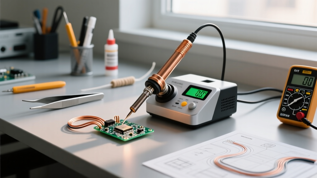
In the current electronics landscape, the price-to-performance ratio of commercial soldering stations has created a massive opportunity for DIY builders. While flagship commercial units like the JBC CD-2BQE or Weller WE1010 command anywhere from $350 to $650, a meticulously engineered DIY soldering station built around modern STM32 microcontrollers and T12 cartridge technology can be assembled for under $75. More importantly, a DIY build allows you to bypass the planned obsolescence and proprietary tip-locking ecosystems of mid-tier commercial brands, giving you direct access to firmware-level PID tuning and unrestricted thermal recovery.
Building your own bench station is not merely a cost-saving exercise; it is an educational deep-dive into power electronics, thermodynamics, and control theory. According to foundational soldering guidelines published by SparkFun, maintaining precise thermal equilibrium at the joint is the single most critical factor in preventing cold joints and thermal pad lift. A DIY station with a custom-tuned PID loop achieves this equilibrium significantly faster than basic analog dial-controlled irons.
Core Component Matrix: T12 vs. C245 Architectures
Before sourcing parts, you must choose your cartridge ecosystem. The Hakko T12 and JBC C245 are the two dominant standards for high-performance DIY builds. Below is a technical comparison to help you select the right architecture for your specific PCB work.
| Specification | Hakko T12 (Clone/Genuine) | JBC C245 (Clone/Genuine) |
|---|---|---|
| Max Power Output | 70W - 75W | 130W |
| Heater Resistance | ~8.0 Ohms | ~2.5 Ohms |
| Optimal PSU Voltage | 24V DC | 24V DC (requires higher amperage) |
| Heat-Up Time (to 350°C) | 6 - 9 seconds | 2 - 4 seconds |
| Estimated BOM Cost | $55 - $70 | $90 - $120 |
Expert Verdict: For 95% of through-hole and standard SMD (0805/0603) work, the T12 architecture is the superior choice due to lower power supply requirements and vastly cheaper replacement tips. Reserve the C245 for heavy ground-plane soldering and large RF connectors.
Step-by-Step Bench Build: The STM32 T12 Route
For this guide, we will focus on the T12 architecture utilizing an STM32-based controller. Avoid outdated Arduino Nano + MAX6675 setups; modern dedicated PCBs sample the thermocouple directly via integrated operational amplifiers, eliminating the need for bulky SPI temperature sensors.
1. Power Supply Selection and Wiring
Do not cheap out on the power supply. A failing PSU can send AC mains voltage to your tip, creating a lethal shock hazard. Use an enclosed, UL-listed switching power supply like the Mean Well LRS-150-24 (24V, 6.25A, approx. $28). Ensure the AC Earth (FG) terminal is securely bonded to the metal chassis of your enclosure. As noted in general electronics safety practices by Electronics Notes, proper grounding is non-negotiable when working with benchtop AC-to-DC conversion.
2. Controller Board Integration
Source a bare STM32 T12 controller board (such as the KSGER V3.1S or Quicko open-source variant, approx. $18). These boards feature a built-in MOSFET for PWM heater control and an op-amp circuit for reading the microvolt-level thermocouple signal generated by the T12 cartridge. Mount the board on brass standoffs inside a PETG or aluminum enclosure. Never use PLA for your enclosure; the ambient heat from the handle resting in the holster will warp PLA within weeks.
3. Handle Wiring and the GX12 Connector
Use a 5-pin GX12 aviation connector for the handle interface. The standard Hakko FX-951 pinout separates the high-current heater lines from the low-voltage thermocouple lines to prevent PWM noise from corrupting the temperature reading:
- Pin 1 & 2: Heater (+24V PWM and GND)
- Pin 3 & 4: Thermocouple (+ and -)
- Pin 5: Earth Ground (Connected to the tip collar via a 1MΩ resistor)
4. Sleep Mode Hardware Interrupts
Modern DIY stations utilize a vibration switch (like the SW-420) inside the handle. Wire this switch to a dedicated hardware interrupt pin on the STM32. When the iron is holstered, the firmware drops the PID setpoint to 150°C (sleeper mode). The physical vibration of picking up the handle triggers the interrupt, instantly waking the MCU and commanding a full 100% PWM duty cycle to recover the tip temperature before it touches the PCB.
Expert PID Tuning for Thermal Recovery
The default PID values on most open-source T12 firmwares are overly conservative to prevent overshoot. However, this results in sluggish thermal recovery when dropping into a large ground plane. To optimize your station, you must manually tune the Proportional (Kp), Integral (Ki), and Derivative (Kd) gains.
The Overshoot Danger: The T12 heater wire is physically embedded inside the copper tip. If Kp is set too high, the internal heater can spike to 500°C+ while the external tip surface is still at 300°C. This will permanently oxidize and destroy the internal heater element. Always tune Kp with a large thermal mass attached to the tip.
Recommended Baseline Tuning for T12-D24 Chisel Tip:
- Kp (Proportional): 15.0 (Provides aggressive initial heating without severe ringing)
- Ki (Integral): 0.8 (Eliminates steady-state error when resting on a pad)
- Kd (Derivative): 12.0 (Dampens the approach to the target temperature, preventing overshoot)
Monitor the serial output of your controller while dragging the tip across a copper-pour test board. If the temperature drops by more than 15°C and takes longer than 3 seconds to recover, increment Kp by 1.5 until you achieve a snappy recovery with less than 5°C of overshoot upon reaching the setpoint.
ESD Grounding and Safety Protocols
When soldering static-sensitive components like MOSFETs, bare-die LEDs, or unshielded RF modules, your DIY station must bleed static charges safely without creating a direct short to earth ground. According to the comprehensive tool and safety guidelines from Adafruit, managing electrostatic discharge (ESD) at the bench is critical for component survival.
Wire Pin 5 of your GX12 connector to the Earth Ground terminal of your Mean Well PSU, but place a 1 Megohm, 1/2 Watt resistor in series. This resistor limits any accidental fault current to microamps (well below the human perception threshold of 5mA) while providing a high-impedance path for static electricity to safely dissipate from the component leads through the tip and into the earth ground.
Troubleshooting Common Failure Modes
Even the best DIY builds encounter edge cases. Here is how to diagnose the three most common T12 station failures:
1. "Tip Not Detected" Error
Cause: The STM32 reads the thermocouple voltage to verify the tip is inserted. If the cartridge contacts are oxidized, or if the internal spring contacts in the handle are compressed, the circuit remains open. Fix: Remove the cartridge and clean the rear contacts with a fiberglass scratch pen. Gently pull the internal springs in the ceramic handle forward with tweezers to ensure firm seating.
2. Thermal Runaway (Tip Glows Red)
Cause: A blown MOSFET (stuck in the closed position) or a severed thermocouple wire inside the handle cord. If the op-amp reads 0V from the thermocouple, the PID assumes the tip is at room temperature and drives the heater at 100% PWM indefinitely. Fix: Implement a firmware watchdog that cuts power if the temperature exceeds 450°C for more than 2 seconds. Physically replace the N-channel MOSFET on the controller board with a logic-level alternative like the IRLZ44N.
3. Audible Whining from the Handle
Cause: The PWM frequency driving the heater is set too low (typically under 1kHz), causing the internal heater coil to vibrate audibly due to magnetostriction. Fix: Access the firmware settings via the encoder dial and increase the PWM frequency to 20kHz. This pushes the switching noise above the range of human hearing and ensures a completely silent bench environment.